Expression 10000XL Revision A
DISASSEMBLY/ASSEMBLY Disassembly Procedure 46
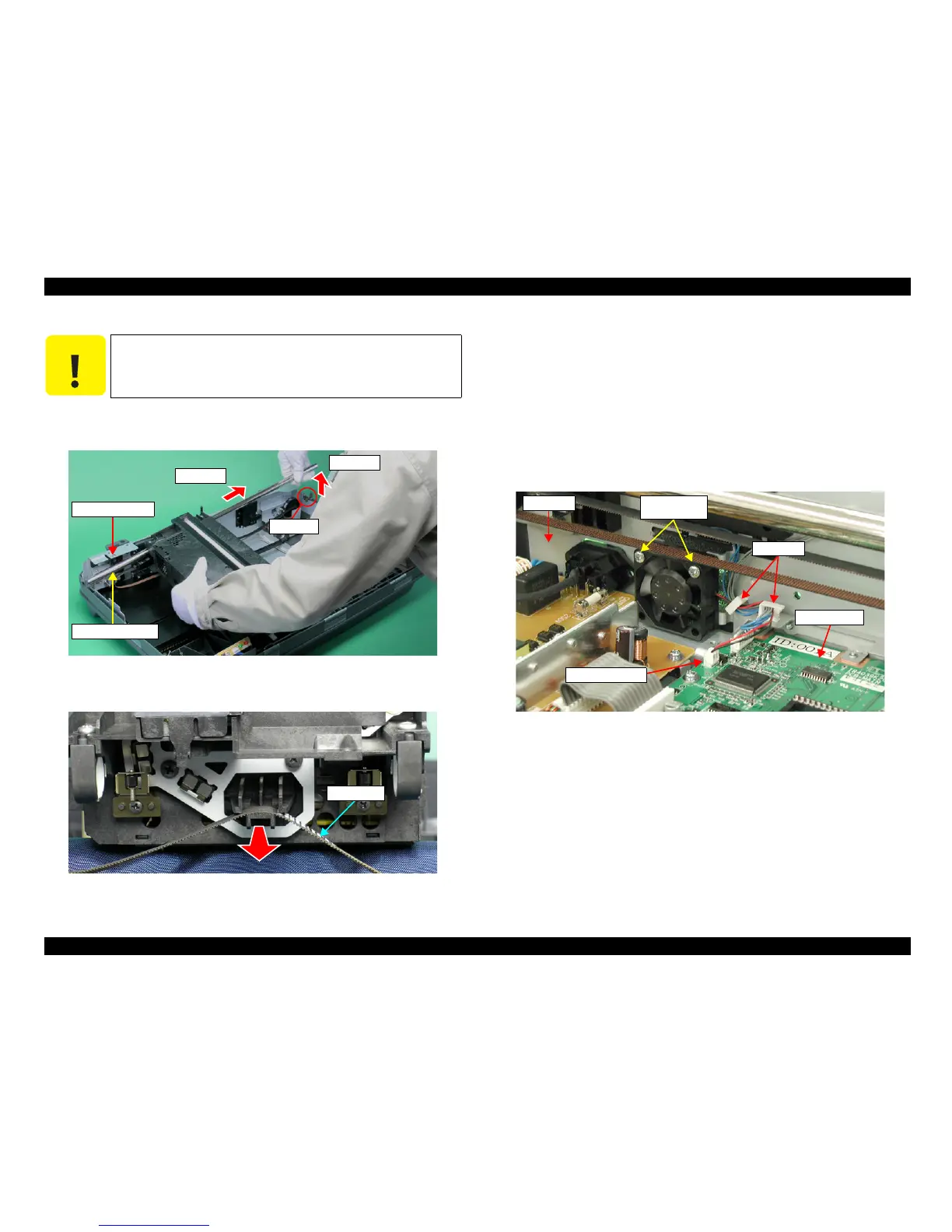
11. Remove the right edge of the Carriage Shaft B from the Bushing and lift the Carriage
Unit and the Carriage Shaft B, then pull the Carriage Shaft B out to remove it.
Figure 4-24. Removal of Carriage Shaft B
12. Remove the CR Belt from the Carriage Unit.
Figure 4-25. Removal of Carriage Unit
4.2.7 Removal of Fan
1. Remove the Power Supply Board Cover.
(Refer to 4.2.4 Removal of Power Supply
Board Step 1 to Step 7.)
2. Remove the Main Board Cover.
(Refer to 4.2.5 Removal of Main Board Step 2 to
Step 5.)
3. Release the Fan Connector Cable from the clamps (2 pcs) and then remove the Fan
Connector Cable from the Main Board.
4. Remove the two screws (CB SCREW, M3x18) that are securing the Fan, and remove
the Fan from the Rear Frame.
Figure 4-26. Removal of Fan
C A U T I O N
When doing the following procedure, be fully careful not to damage
the Carriage Shaft B by the Rear Frame or something else.
Bushing
Carriage Shaft B
Step 11-2
Step 11-1
Rear Frame
CR Belt
Fan Connector
Main Board
Clamps
M3x18
(50±10Ncm)
Frame
 Loading...