Expression 10000XL Revision A
DISASSEMBLY/ASSEMBLY Disassembly Procedure 55
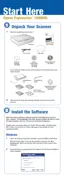
4.2.12.4 Removal of OPTION I/F Connector Cable
1. Remove the OPTION I/F Connector Cable (2 pcs) from the TPU Main Board.
(Refer
to 4.2.12.3 Removal of TPU Main Board Step 1 to Step 5.)
2. Remove the OPTION I/F Connector Cable from the clamps (6 pcs).
3. Remove the two screws (CB SCREW, M4x6:1 pc, CBP, M4x10:1 pc) that are securing
the Earth Cable and Tie Lap, and remove the OPTION I/F Connector Cable.
Figure 4-43. Removal of OPTION I/F Connector Cable
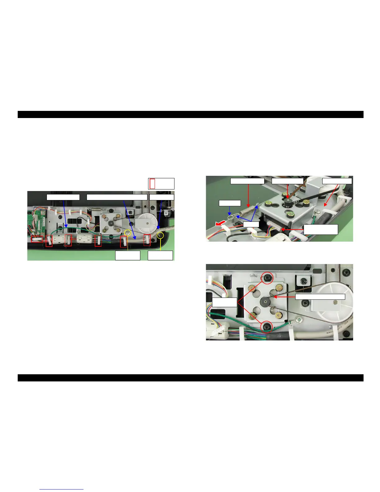
4.2.12.5 Removal of TPU CR Motor Belt/TPU CR Motor
1. Move the TPU Carriage Unit to the center.
(Refer to 4.2.12.3 Removal of TPU Main
Board Step 1 to Step 2.)
2. Disconnect the TPU CR Motor Connector Cable from the TPU CR Motor.
3. Pull the A portion of the extension spring in a direction of the arrow, and release it
from the two hooks of the Fixing Plate A, then remove the extension spring.
Figure 4-44. Removal of TPU CR Motor Connector/Extension Spring
4. Remove the two screws (CP(S-P2), M4x8) that are securing TPU CR Motor Unit.
Figure 4-45. Removal of Screws of TPU CR Motor Unit (2)
Earth Cable Tie Lap
M4x6
(50±10Ncm)
M4x10
(50±10Ncm)
OPTION I/F Connector Cable
Clamps
TPU CR MotorExtension Spring Fixing Plate A
A portion
Hooks
TPU CR Motor
Connector Cable
TPU CR Motor Unit
M4x8
(50±10Ncm)
 Loading...