Expression 10000XL Revision A
DISASSEMBLY/ASSEMBLY Disassembly Procedure 50
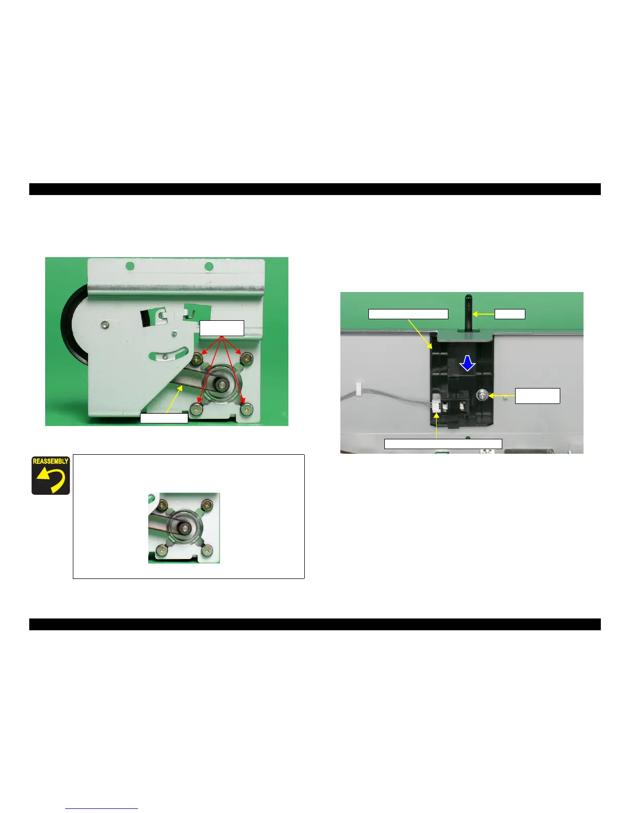
8. Remove the four screws (M3x10) that are securing the CR Motor, and remove the CR
Motor.
9. Remove the Motor Belt from the HP Tension Unit.
Figure 4-34. Removal of CR Motor and Motor Belt
4.2.11 Removal of Open/Close Sensor Unit
1. Remove the Carriage Unit.
(Refer to 4.2.6 Removal of Carriage Unit and Carriage
Shaft A/B)
2. Disconnect the Open/Close Sensor Connector Cable.
3. Remove the one screw (CP(S-P2), M4x10) that is securing the Open/Close Sensor
Unit, and slide down and remove the Open/Close Sensor Unit.
Figure 4-35. Removal of Open/Close Sensor Unit
When reinstalling the CR Motor screws, tighten them in order of (1),
(2), (3) and (4).
M3x10
(80±20Ncm)
Motor Belt
(1)
(3) (4)
(2)
Open/Close Sensor Unit
Open/Close Sensor Connector Cable
Lever
M4x10
(50±10Ncm)
 Loading...