Expression 10000XL Revision A
DISASSEMBLY/ASSEMBLY Disassembly Procedure 47
4.2.8 Removal of Power Switch
1. Remove the Power Switch Connector Cable (2 pcs) from the Power Supply
Board.
(Refer to 4.2.4 Removal of Power Supply Board Step 1 to Step 8.)
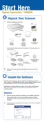
2. Remove the two screws (CBP, M3x8) that are securing the Cover B, and slide the
Cover B to remove it in a right oblique direction.
Figure 4-27. Removal of Cover
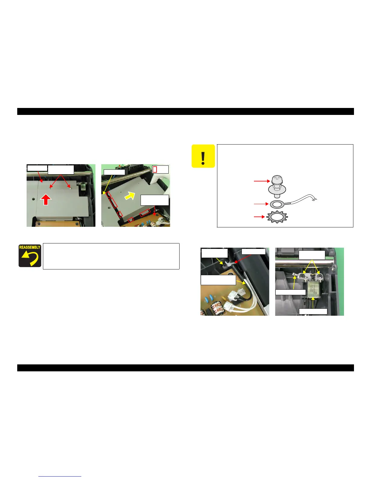
3. Remove the one screw (CBP, M3x10) that is securing the Tie Lap, and release the
Power Switch Connector Cable.
4. Remove the two screws (CBP, M4x10) that are securing the Power Switch and Earth
Cable, and remove the Power Switch.
Figure 4-28. Removal of Power Switch
Be sure to put the Rib of the Cover B under the Cover A and Power
Supply Board.
M3x8
(50±10Ncm)
Cover B
Ribs
Cover A
Power Supply
Board
C A U T I O N
When doing the following procedure, be fully careful not to
damage the Carriage Shaft A by the screwdriver.
There is a washer between the Earth and the threaded screw
hole. Be sure not to lose the washer.
Screw
Earth
Washer
Tie Lap
M3x10
(50±10Ncm)
Power Switch
Connector Cable
Earth Cable
Power Switch
M4x10
(70±10Ncm)
 Loading...