Expression 10000XL Revision A
DISASSEMBLY/ASSEMBLY Disassembly Procedure 42
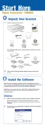
11. Remove the four screws (CP(S-P1), M3x6) that are securing the Power Supply Board.
12. Lift the Power Supply Board avoiding the Power Switch Connector Cable, and slide
and remove it toward you.
Figure 4-14. Removal of Power Supply Board
4.2.5 Removal of Main Board
1. Remove the Housing Upper.
(Refer to 4.2.3 Removal of Housing Upper)
2. Release the Carriage Lock.
(Refer to 4.2.4 Removal of Power Supply Board Step 3 )
3. Move the Carriage Unit to the left edge.
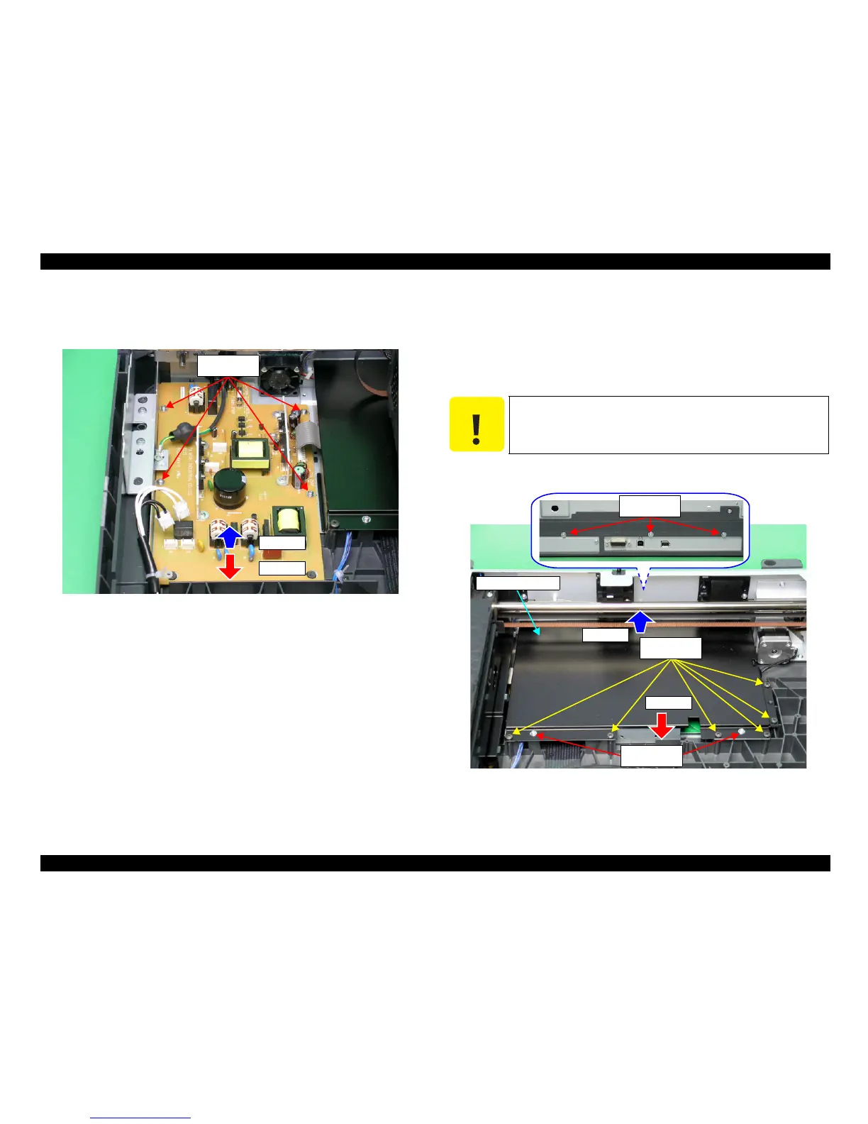
4. Remove the 11 screws (CBP M4x10:6 pcs, CP(S-P1) M3x6:2 pcs, CP(S-P2) M3x12:3
pcs) that securing the Main Board Cover.
5. After lifting the Main Board Cover, pull and remove it toward you.
Figure 4-15. Removal of Main Board Cover
M3x6
(60±10Ncm)
Step 12-2
Step 12-1
C A U T I O N
When doing the following procedure, be fully careful not to damage
the Carriage Shaft B.
Main Board Cover
M3x12
(100±20Ncm)
M3x6
(100±20Ncm)
M4x10
(70±10Ncm)
Step 5-1
Step 5-2
 Loading...