Expression 10000XL Revision A
DISASSEMBLY/ASSEMBLY Disassembly Procedure 43
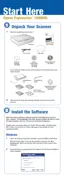
6. Remove the Connector Cables and Harness, shown in
Refer to Figure 4-16
, from the
Main Board.
CN1/CN13: Carriage FFC
CN2: Motor Connector Cable
CN3: HP Sensor/Open/Close Sensor Connector Cable
CN4: Harness
(Refer to 4.2.4 Removal of Power Supply Board Step 10 )
CN5: Fan Connector Cable
CN6: Panel Connector Cable
7. Release the Fan Connector Cable, HP Sensor and Open/Close Sensor Connector Cable
from the clamp.
Figure 4-16. Removal of Main Board (1)
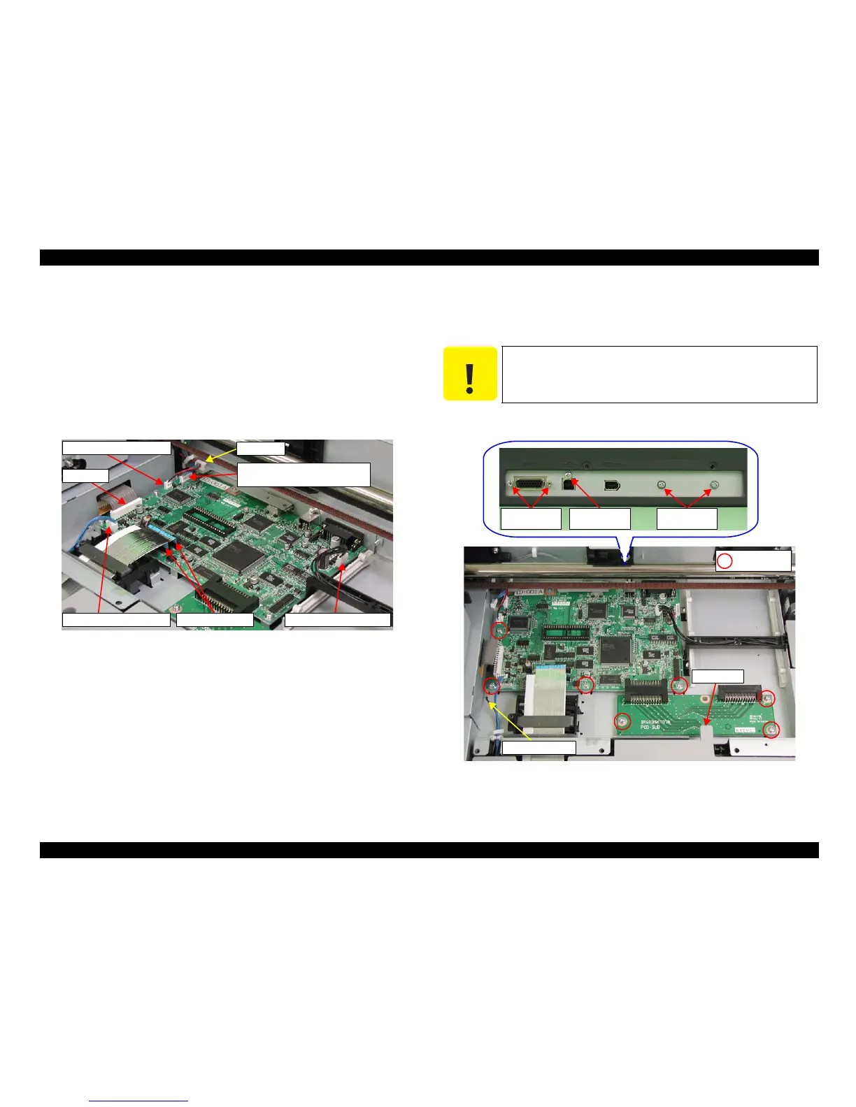
8. Remove the 12 screws (SCREW HSH, M3x10:2 pcs, CB SCREW, M3x8:1 pc, CP(S-
P1), M3x6:9 pcs) that are securing the Main Board and Earth Cable, and remove the
Main Board.
9. Remove the Main Board avoiding the protrusion of the Cover A.
Figure 4-17. Removal of Main Board (2)
Carriage FFC
Fan Connector Cable
Harness
Panel Connector Cable Motor Connector Cable
HP Sensor, Open/Close Sensor
Connector Cable
Clamp
C A U T I O N
When doing the following procedure, be fully careful not to damage
the Carriage Shaft B.
M3x10
(70±20Ncm)
M3x8
(50±5Ncm)
M3x6
(50±10Ncm)
M3x6
(50±10Ncm)
Earth Cable
Protrusion
 Loading...