Expression 10000XL Revision A
DISASSEMBLY/ASSEMBLY Disassembly Procedure 48
4.2.9 Removal of Panel Board
1. Remove the Housing Upper.
(Refer to 4.2.3 Removal of Housing Upper)
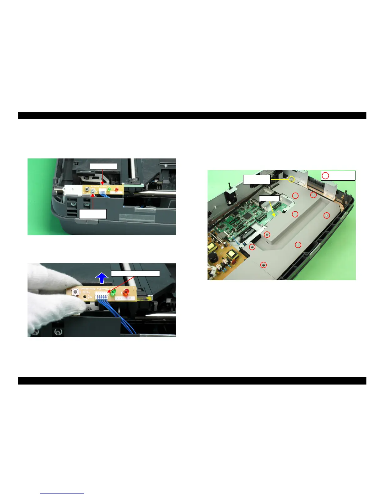
2. Remove the one screw (CP(S-P1), M3x6) that is securing the Panel Board.
Figure 4-29. Removal of Panel Board (1)
3. Lift the Panel Board a little and remove the Panel Connector Cable from the Panel
Board, then remove the Panel Board.
Figure 4-30. Removal of Panel Board (2)
4.2.10 Removal of HP Tension Unit/CR Motor
1. Remove the Carriage Unit.
(Refer to 4.2.6 Removal of Carriage Unit and Carriage
Shaft A/B)
2. Remove the 9 screws (CB SCREW, M3x8:1 pc, CBP, M3x8:8 pcs) that are securing
the Cover A, and remove the Cover A.
Figure 4-31. Removal of Cover A
Panel Board
M3x6
(60±10Ncm)
Panel Connector Cable
Cover A
CB M3x8
(50±20Ncm)
CBP M3x8
(50±20Ncm)
 Loading...