Expression 10000XL Revision A
OPERATING PRINCIPLES Electrical Circuit Operation Overview 23
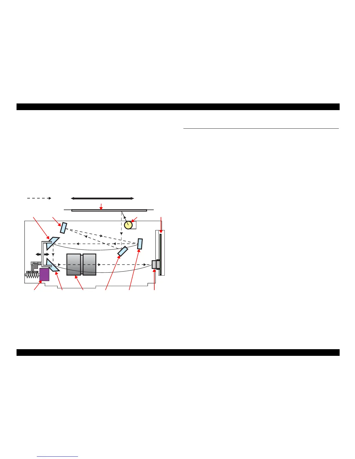
2.2.3 Carriage Optical System Mechanism
Since the color CCD line sensor is used as a scanning device, the light source is single
and color separation into R, G and B is achieved by the Color Filter on the CCD
Sensor.
The light coming out of the light source (high-intensity cold cathode xenon lamp) in
the Carriage Unit is applied to the document surface, its image is scanned in the main
scanning direction, then reflected by multiple mirrors in the Carriage as a reflective
light, and detected by the CCD.
In order to achieve auto focusing, the Mirror Unit consisting of Mirror 4 and Mirror 5
is moved by the Auto Focus Motor to adjust the distance from the document surface to
the Lens/CCD Sensor.
Figure 2-4. Mirror/Lens Mechanism
2.3 Electrical Circuit Operation Overview
2.3.1 Control Circuit Operation
The control circuit of this scanner consists of the following circuits.
PCB-MAIN Board (Main control circuit board)
PCB-CCD Board (CCD sensor board/installed on the Carriage)
DU2L3B158 Board (Power Supply Board)
PCB-PANEL Board (Operation panel board)
PCB-TPU MAIN Board (TPU-Main control circuit board)
The control performed by the PCB-MAIN Board and PCB-CCD Board that form the
heart of the control circuit will be explained in the order of size detection by the
Document Size Detection Sensor, scanning, and image signal processing.
1. PCB-CCD Board (CCD image sensor)
Photoelectric transfer processing (transduces the reflected light (light energy)
from the document surface into electrical energy (electric charge))
Amplification processing
2. PCB-MAIN Board (Scanned image data processing)
Most of the following processings are performed by the ASIC (IC2) on this Board.
A/D conversion processing (converts the scanned image data generated as an
analog electrical signal into a 16-bit digital signal.)
Shading correction processing (scanned image data correction using white
and black reference values)
Various image correction processings (executed on the basis of the setting
conditions from the host, e.g. gamma correction, color correction, and
halftone correction.)
The above processings are performed, and the scanned image data are finally output to
the host.
Lamp
Front Back
Scanned image
Mirror 1Lens
Document
CCD Board
Mirror 3
Mirror 2
Mirror 5
CCD Sensor
Auto Focus Motor
Mirror 4
 Loading...