Expression 10000XL Revision A
DISASSEMBLY/ASSEMBLY Disassembly Procedure 49
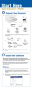
3. Disconnect the CR Motor Connector Cable from the CR Motor.
4. Remove the one screw (CP(S-P1), M3x6) that is securing the Pulley Fixing Plate.
5. Pull and remove the Pulley Fixing Plate out of the Shaft.
Figure 4-32. Removal of Pulley Fixing Plate
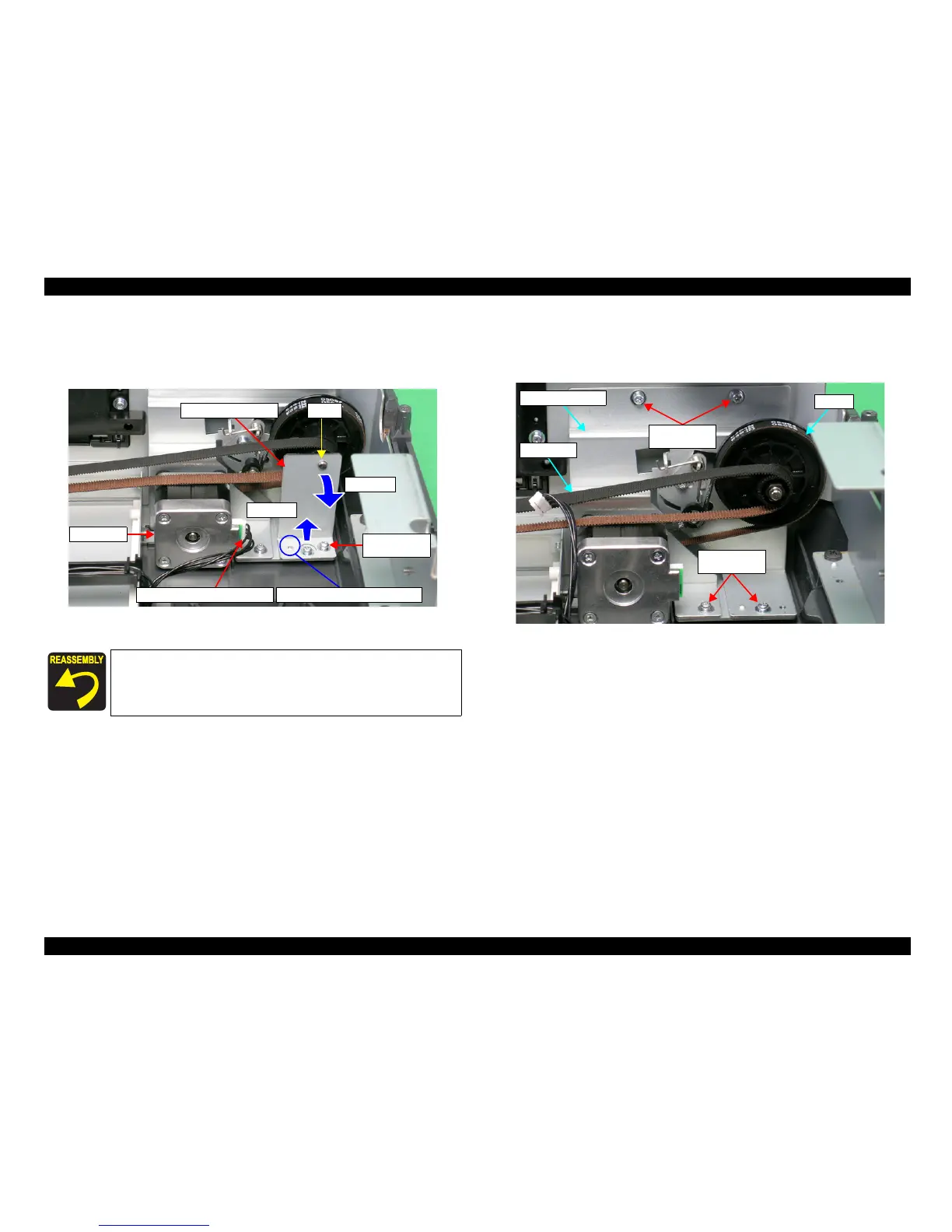
6. Remove the CR Belt from the Pulley.
7. Remove the four screws (CP(S-P1), M3x6) that are securing the HP Tension Unit, and
remove the HP Tension Unit.
Figure 4-33. Removal of CR Belt/HP Tension Unit
When reinstalling the Pulley Fixing Plate, be sure to match the hole
and dowel indicated in
Figure 4-32
.
Step 5-1
Pulley Fixing Plate Shaft
CR Motor Connector Cable
CR Motor
M3x6
(100±20Ncm)
Positioning Holes and Dowels
Step 5-2
M3x6
(100±20Ncm)
M3x6
(100±20Ncm)
CR Belt
Pulley
HP Tension Unit
 Loading...