A3 Size Color Flat Bed Scanner GT-30000 Revision A
PRODUCT OUTLINE Operation Specifications 20
"
Select SW of SCSI Data Bus Length (See "Figure 1-6. SCSI ID and
SCSI Data Bus Length switch")
!
Position W: SCSI works in 8bit or 16bit in accordance with
negotiation.
!
position N: SCSI works in only 8bit data bus
"
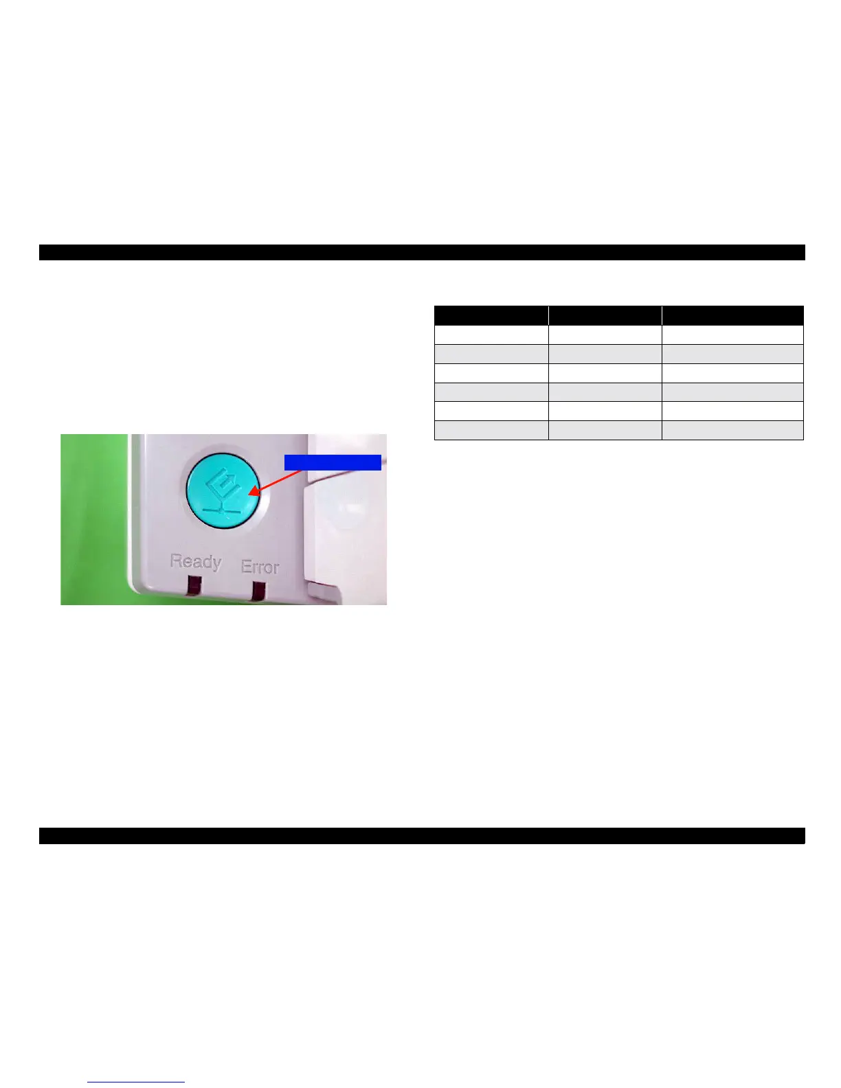
Start button
!
Start scanning (In case of network connection)
!
Wake up scanner application software (In case of local connection)
Figure 1-8. Start button
1.4.2 Indicators
If an error occurs, determine the error type referring to the status of the READY
and ERROR LED indicators.
"
READY (Green LED)
Comes on when the scanner is ready to send and receive data.
Blink in combination with the ERROR LED when an error occurs.
"
ERROR (Red LED)
Indicates the Error.
NOTE: See "Chapter 3.1.1 Errors and Causes of Errors" for details on
solving the error.
Terminator switch
Table 1-11. Indicator Status and Corresponding Errors
READY LED (Green) ERROR LED (Red) Condition
Lighting Turning off Ready
Blinking Turning off Under Scanning, Initialization
Lighting Lighting Command Error
Turning off Blinking Interface Error
Blinking Blinking Fatal Error
Lighting Turning off Option Error (ADF Error)
 Loading...


