A3 Size Color Flat Bed Scanner GT-30000 Revision A
TROUBLESHOOTING Overview 32
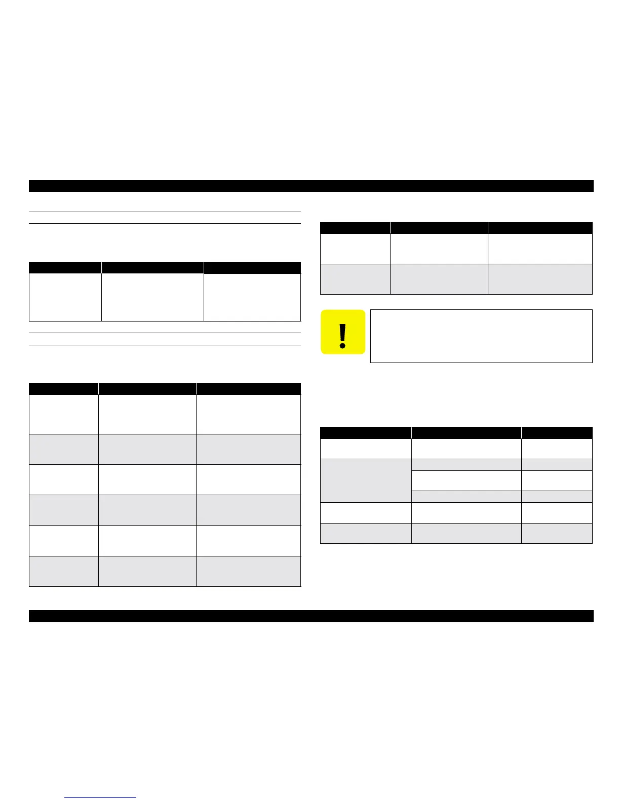
MOTORS
Condition: Disconnect from the connector and measure with the cable
connected to the motor.
SENSORS
Condition: Test the sensors with the power on.
3.1.2.2 Troubleshooting Other Errors
See the table below for miscellaneous errors not covered in the previous sections.
See subsequent pages for troubleshooting specific to each problem with major
units above.
Table 3-5. Motor Check Points
Motor Test Point Signal Level
Motor (for driving the
mirror)
<Cable connector>
Between Pins 1 and 3
Between Pins 1 and 4
Between Pins 2 and 5
Between Pins 2 and 6
Approximately 0.56
Ω
Table 3-6. Sensor Check Points
Motor Test Point Signal Level
HP sensor (Mirror)
<PBA-CONNECT board>
CN1: Pin 7 (Signal)
Pin 6 (GND)
H: Mirror unit is in the home
position.
L: Mirror unit is outside its
home position.
Open sensor
<PBA-CONNECT board>
CN4: Pin 2 (Signal)
Pin 1 (GND)
H: Cover closed
L: Cover open
Document size
sensor 1
<PBA-CONNECT board>
CN10: Pin 6 (Signal)
Pin 4 (GND)
H: Document not present
L: Document present
Document size
sensor 2
<PBA-CONNECT board>
CN10: Pin 3 (Signal)
Pin 1 (GND)
H: Document not present
L: Document present
Document size
sensor 3
<PBA-CONNECT board>
CN10: Pin 9 (Signal)
Pin 7 (GND)
H: Document not present
L: Document present
Document size
sensor 4
<PBA-CONNECT board>
CN9: Pin 3 (Signal)
Pin 1 (GND)
H: Document not present
L: Document present
Document size
sensor 5
<PBA-CONNECT board>
CN9: Pin 9 (Signal)
Pin 7 (GND)
H: Document not present
L: Document present
Document size
sensor 6
<PBA-CONNECT board>
CN9: Pin 6 (Signal)
Pin 4 (GND)
H: Document not present
L: Document present
C A U T I O N
Be careful not to short-circuit the signals while
checking them.
Table 3-7. In case of abnormal performance
Phenomenon Description Refer to Flowchart
The scanner doesnt
operate at power on.
READY LED does not light. Flowchart 3-1
Fatal Error is indicated
and does not clear after
the scanner is turned off
and back on
CR does not move. Flowchart 3-2
Abnormal movement of CR, such
as crashing into the frame.
Flowchart 3-3
Lamp does not light. Flowchart 3-4
Communication Error is
indicated
SCSI not set properly or
defective
Flowchart 3-5
The scanner does not scan
images properly.
Black lines, White banding, and
so on
Flowchart 3-6
Table 3-6. Sensor Check Points
Motor Test Point Signal Level
 Loading...


