A3 Size Color Flat Bed Scanner GT-30000 Revision A
DISASSEMBLY & ASSEMBLY Disassembly Procedures 51
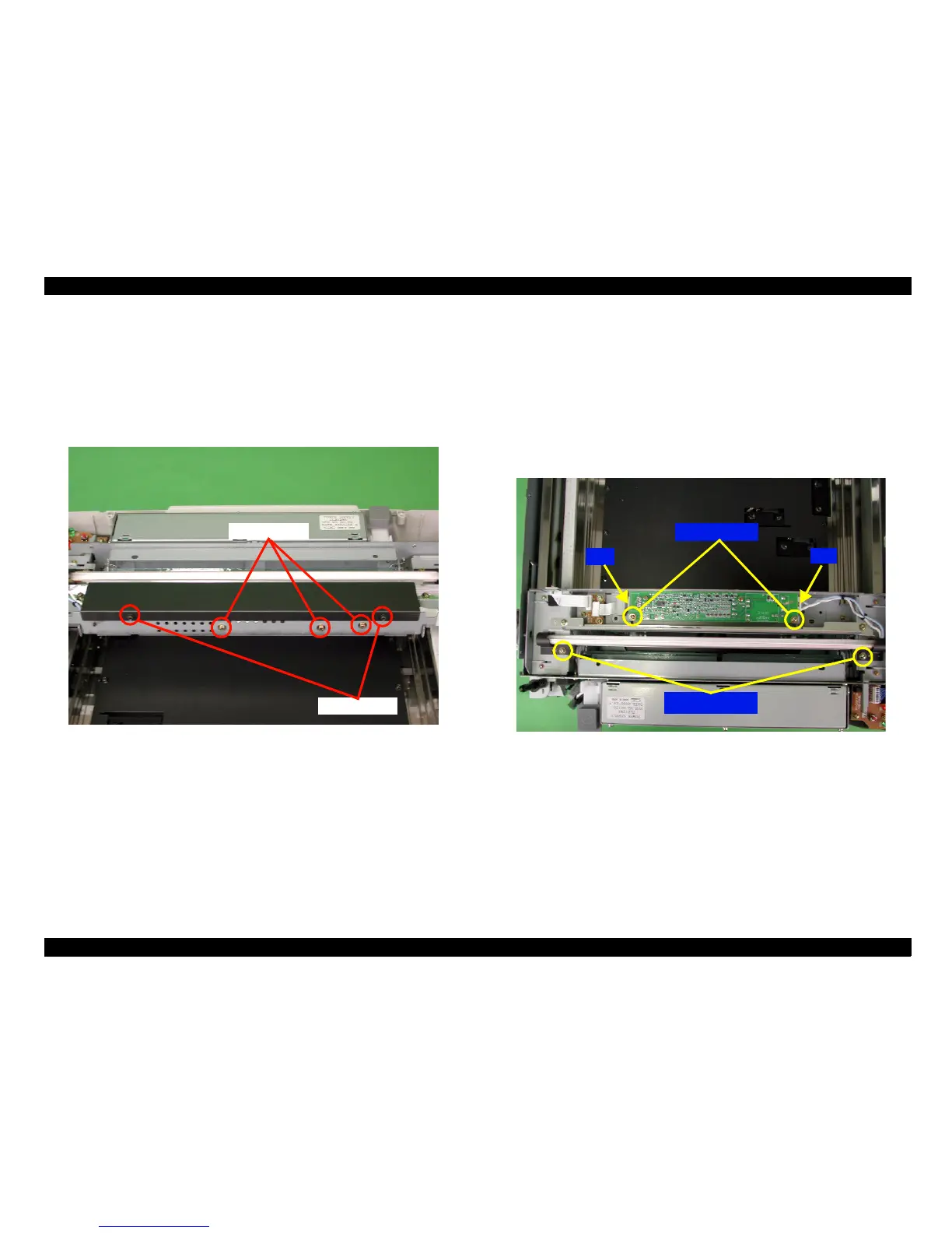
4.2.2.7.1 Lamp Cover Removal
1. Remove the glass frame assembly. ("Chapter 4.2.2.5 Glass Frame
Assembly Removal".)
2. Remove the two screws (No.7) which are securing the lamp cover, and
then remove the lamp cover.
Figure 4-18. Lamp Cover Removal
4.2.2.7.2 Lamp Removal
1. Disconnect the lamp cable from the connector (CN2) on the inverter circuit
board.
2. Remove the two screws (No.8) which are securing the lamp, and then
remove the lamp. (See "Figure 4-19. Lamp and Inverter Circuit Board
Removal".)
4.2.2.7.3 Inverter Circuit Board Removal
1. Remove the five screws (No.8) which are securing the inverter circuit
board.(See "Figure 4-19. Lamp and Inverter Circuit Board Removal" and
"Figure 4-20. Mechanism internal cover Removal")
2. Disconnect the cables from the connectors (CN1 and CN2) on the inverter
circuit board, and then remove the board. (See "Figure 4-19. Lamp and
Inverter Circuit Board Removal".)
Figure 4-19. Lamp and Inverter Circuit Board Removal
4.2.2.8 Mechanism internal cover removal Removal
1. Remove the glass frame assembly. (See "Figure 4.2.2.5. Glass Frame
Assembly Removal".)
2. Remove the twelve screws (No.9) which are securing the Mechanism
internal cover removal to the scanner chassis.
3. Lift the Mechanism internal cover up to remove it. (See "Figure 4-20.
Mechanism internal cover Removal".)
Screws
ScrewsScrews
Screws(No.
(No.(No.
(No.
7
)
))
)
Screws
ScrewsScrews
Screws(No.
(No.(No.
(No.
8
)
))
)
Screws
ScrewsScrews
Screws(No.
(No.(No.
(No.
8
)
))
)
CN1
CN1CN1
CN1
CN2
CN2CN2
CN2
Screws
ScrewsScrews
Screws(No.
(No.(No.
(No.
8
)
))
)
 Loading...


