A3 Size Color Flat Bed Scanner GT-30000 Revision A
DISASSEMBLY & ASSEMBLY Disassembly Procedures 46
4.2.2 Scanner Mechanism Disassembly
This section describes the removal procedures for the main components of the
scanner mechanism.
4.2.2.1 Power Supply assembly Removal
1. Remove the four screws (No.5) which are securing the [power supply
assembly to the scanner mechanism, and then remove the power supply
assembly. (See "Figure 4-9. Power Supply assembly Removal".)
2. Disconnect the power supply assembly CN1 and CN2 connectors
(between the power supply assembly and the scanner mechanism).
Figure 4-9. Power Supply assembly Removal
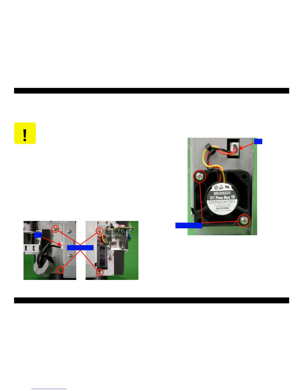
4.2.2.2 Cooling Fan Removal
1. Disconnect the cooling fan CN1 connector.
2. Remove the two screws (No.10) which are securing the cooling fan to the
power supply assembly, and then remove the cooling fan. (See "Figure
4-10. Cooling Fan Removal".)
Figure 4-10. Cooling Fan Removal
4.2.2.3 Power Supply Circuit Board Removal
1. Remove the 11 screws (No.11: 3 and No.12: 8) which are securing the
power supply assembly cover, and then remove the cover. (See "Figure
4-11. Power Supply Circuit Board Removal (a)".)
2. Remove the power supply circuit board.
C A U T I O N
!
A high degree of precision control is required of the
scanner mechanism, and so extremely precise
installation and adjustment are carried out during the
manufacturing process.
Therefore, never disassemble any scanner parts
unless specifically instructed to do so in this section
of the manual.
!
When removing the scanner mechanism from the
housing to carry out disassembly, be sure to place the
scanner mechanism on top of the leveling tool before
disassembling it.
Screws
ScrewsScrews
Screws(No.
(No.(No.
(No.
5
)
))
)
CN1
CN1CN1
CN1
Screws
ScrewsScrews
Screws(No.
(No.(No.
(No.
10
)
))
)
CN1
CN1CN1
CN1
 Loading...


