A3 Size Color Flat Bed Scanner GT-30000 Revision A
DISASSEMBLY & ASSEMBLY Disassembly Procedures 47
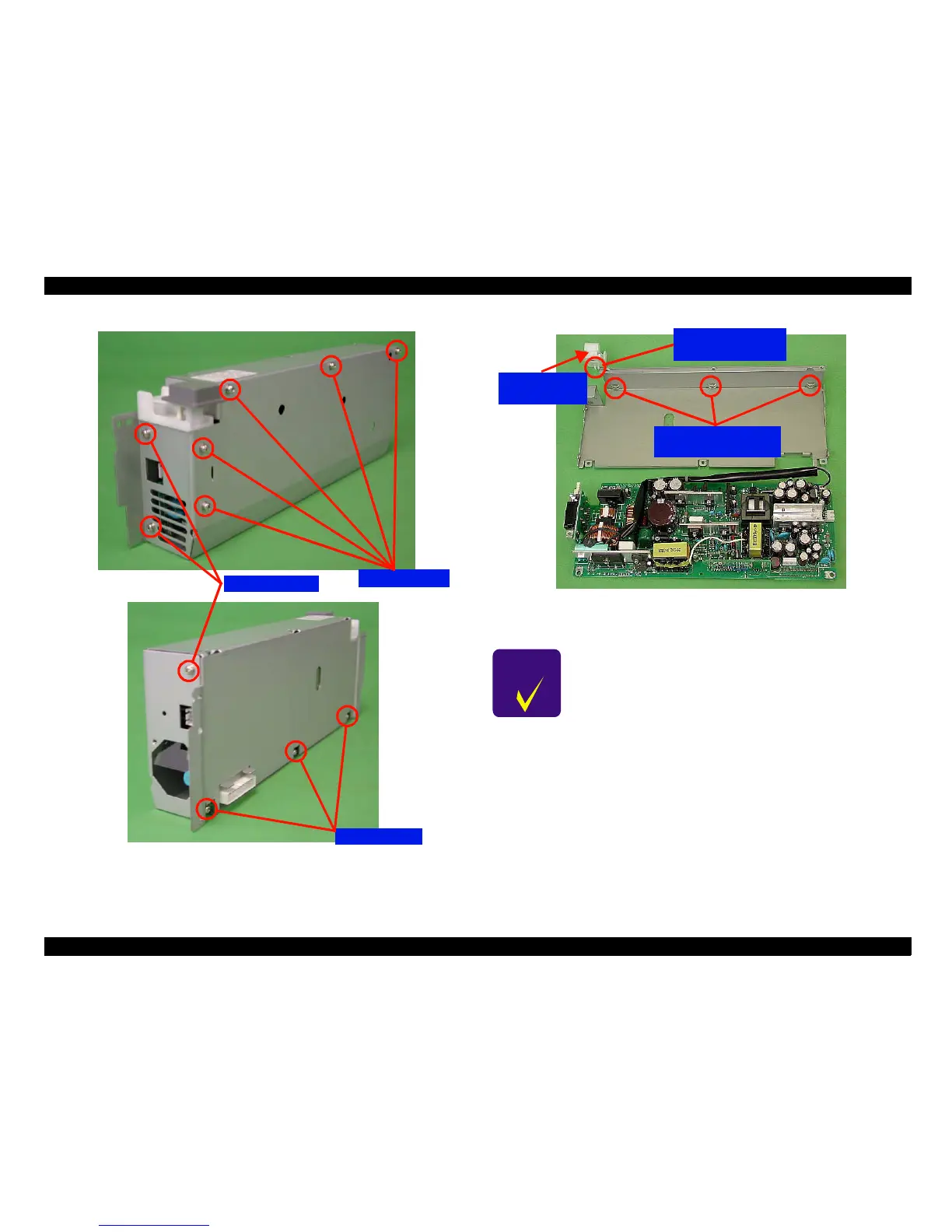
Figure 4-11. Power Supply Circuit Board Removal (a)
Figure 4-12. Power Supply Circuit Board Removal (b)
Screws
ScrewsScrews
Screws(No.
(No.(No.
(No.
11
)
))
)
Screws
ScrewsScrews
Screws(No.
(No.(No.
(No.
12
)
))
)
Screws
ScrewsScrews
Screws(No.
(No.(No.
(No.
12
)
))
)
C H E C K
P O I N T
!
Be careful not to break the tabs when removing the
power switch cover.
!
When installing the power supply board, make sure
that the board is fitting securely into the guides.
!
When installing the power supply board, set the
height of the power switch as shown in "Figure 4-13.
Power Switch Height" on the following page.
Push the tabs
inward to remove
Power supply board
mounting guides
Power Switch
Cover
 Loading...


