A3 Size Color Flat Bed Scanner GT-30000 Revision A
DISASSEMBLY & ASSEMBLY Disassembly Procedures 53
3. Secure the CR motor assembly to the scanner mechanism by tightening
the screws. (See "Figure 4-21. CR Motor Assembly Removal".)
Figure 4-21. CR Motor Assembly Removal
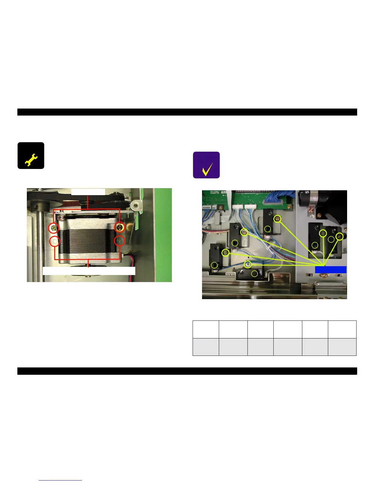
4.2.2.10 Document Size Sensor Removal
1. Remove the circuit board and sensor cover. (See "Chapter 4.2.2.8
Mechanism internal cover removal Removal".)
2. Remove each of the screws (No. 8) which are securing the document size
sensors to the scanner chassis, and then disconnect each of the
connectors (CN1) from the document size sensors.
3. Take the document size sensors upward and remove them. (See "Figure
4-22. Document Size Sensor Removal".)
Figure 4-22. Document Size Sensor Removal
A D J U S T M E N T
R E Q U I R E D
When re-installing the CR motor assembly, be sure to
adjust the belt tension by referring to "Chapter 5.2 Belt
Tension Adjustment".
Screws(No.13)
CR Motor Assembly Positioning Dowels
C H E C K
P O I N T
When installing the document size sensors, make sure
that the connectors are connected correctly. (See "Table
4-4 Document Size Sensor and Cable Colors".)
Table 4-4. Document Size Sensor and Cable Colors
Document
Size
Sensor 1
Blue/Blue/
Blue
Document
Size
Sensor 3
Blue/Blue/
White
Document
Size
Sensor 3
Light Blue/
White/White
Document
Size
Sensor 2
Blue/
Light Blue/
Light Blue
Document
Size
Sensor 4
White/White/
White
Document
Size
Sensor 4
Light Blue/
Light Blue/
Light Blue
Screws
ScrewsScrews
Screws(
((
(
No.8
)
))
)
1
11
1
2
22
2
3
33
3
4
44
4
5
55
5
6
66
6
 Loading...


