A3 Size Color Flat Bed Scanner GT-30000 Revision A
TROUBLESHOOTING Overview 36
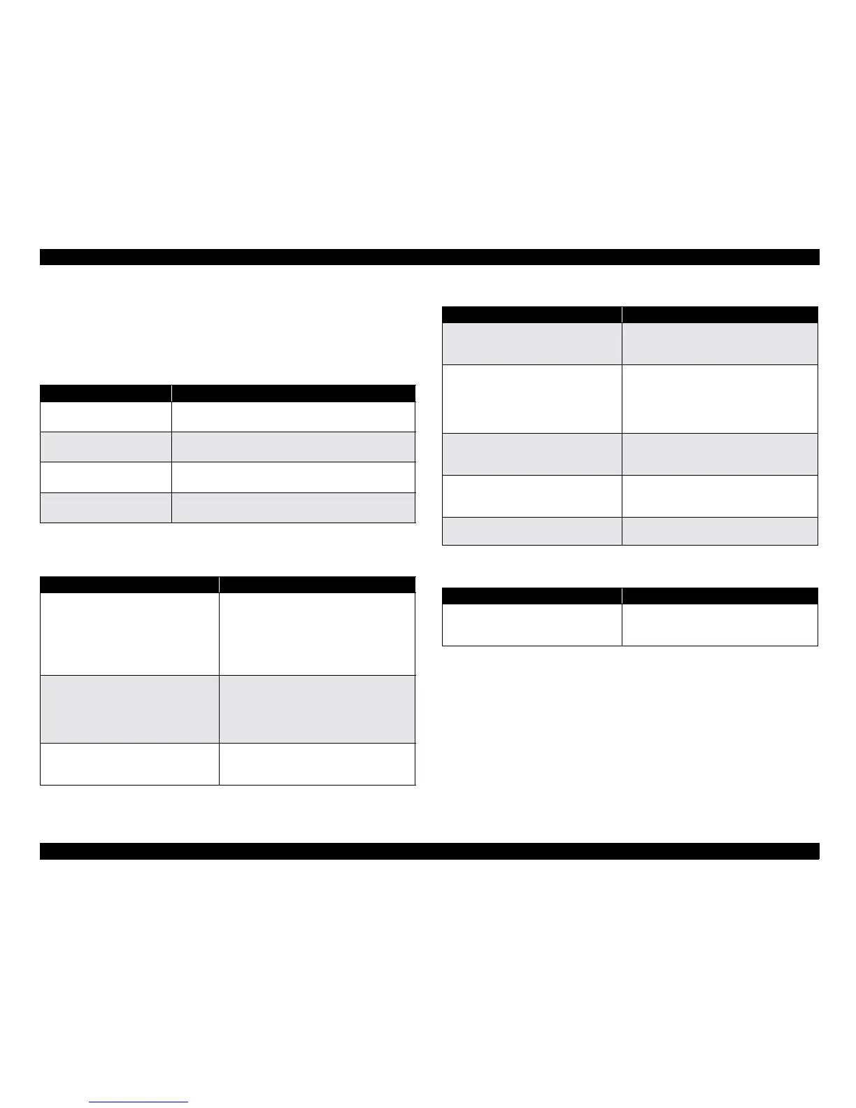
3.1.3 Troubleshooting Circuit Board Errors
This section describes the check points for the electrical circuit boards.
3.1.3.1 Power Supply Board (PWS-POWER Board)
3.1.3.2 Control Circuit Board (PBA-MAIN Board)
Table 3-8. PWS-POWER Board Troubleshooting
Phenomenon Check Points
<Abnormal voltage>
+5VDC is not output.
Check the input voltage for Z7 (SI-3033).
5 pin
<Abnormal voltage>
+24 VDC is not output.
Check the voltage waveform between D-S of 013.
<Abnormal voltage>
+12 VDC is not output.
Check the input voltage for Z4 (
µ
PC78M12).
Input pin
<Abnormal voltage>
+3.3 VDC is not output.
Check the voltage waveform between D-S of 012.
Table 3-9. PBA-MAIN Board Troubleshooting
Phenomenon Check Points
<No operation at all>
Reset IC is defective.
Check the input/output signal waveforms
for the following pins of the reset IC
connector (IC4):
Pin 8 (for RESET signal)
Pin 5 (for +5V input)
Pin 3 (for WD output)
<No operation at all>
EEPROM access error
Check the CPU (IC1) for the ROM access
signal waveforms output from the following
pins:
Pin 2 (for ROM_CS signal)
Pin 91 (for RD signal)
<No operation at all>
CPU is defective.
Check the CPU (IC1) for the signal
waveform input to the following pin:
Pin 86 (for EXTAL input)
<Fatal Error>
Carriage does not stop at the home
position.
Check the CPU (IC1) for the signal
waveform input to the following pin:
Pin 32 (for HPS signal)
<Fatal Error>
Lamp does not light.
Check the output signal waveform and the
+24 V output voltage level at the CPU
connector (IC1):
Pin 115 (for LAMP signal)
Pin 5 (for +24V output)
<Fatal Error>
White standard level is not read
properly.
Main cause: ASIC (IC2) is defective.
(Replace PBA-MAIN board.)
<Communication Error>
Bi-directional I/F or SCSI I/F are
defective.
Main cause: ASIC (IC3) and ASIC (IC2) are
defective. (Replace PBA-MAIN board.)
<Image is read abnormally>
Main cause: ASIC (IC2) is defective.
(Replace PBA-MAIN board.)
Table 3-10. PBA-CONNECT Board Troubleshooting
Phenomenon Check Points
<Fatal Error>
Motor drive circuit is defective.
Check the Drive IC (IC1) Phase drive signal
waveform output to the following pin:
Pin 11 (for CLK signal)
Table 3-9. PBA-MAIN Board Troubleshooting (continued)
Phenomenon Check Points
 Loading...


