A3 Size Color Flat Bed Scanner GT-30000 Revision A
DISASSEMBLY & ASSEMBLY Disassembly Procedures 52
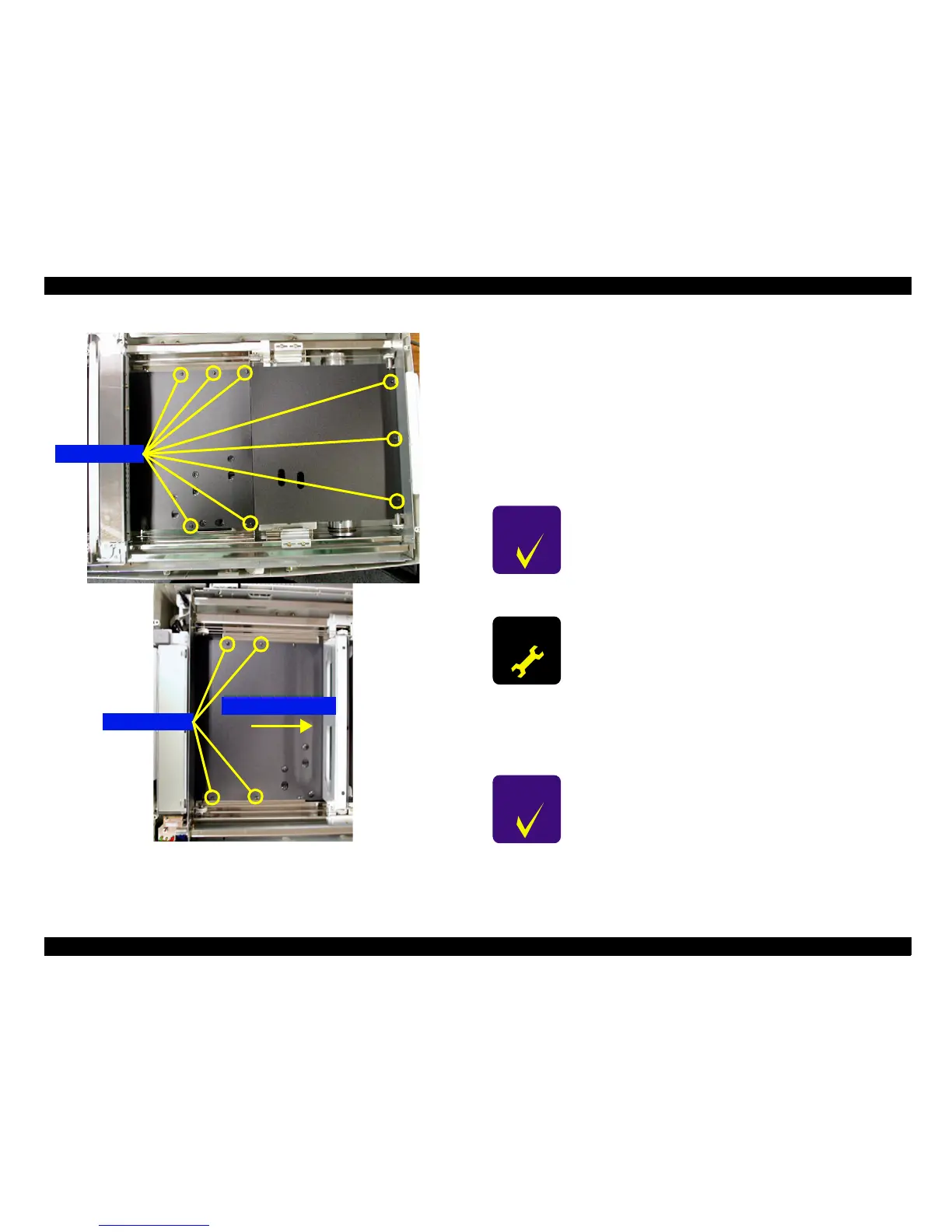
Figure 4-20. Mechanism internal cover Removal
4.2.2.9 CR Motor Assembly Removal
This section describes the procedures for removing the CR motor assembly
which drives the carriage mechanism (mirror/lamp).
1. Remove the lens and CR motor assembly cover. (See "Chapter 4.2.2.8
Mechanism internal cover removal Removal".)
2. After disconnecting the CR motor assembly connector CN1, remove the
two screws (No.13) and then remove the motor. (See "Figure 4-21. CR
Motor Assembly Removal".)
4.2.2.9.1 CR Motor Assembly Installation
1. Place the CR motor assembly into the scanner mechanism, and attach the
belt.
2. Apply tension to the belt using the belt tension adjustment tool. (For
details, see "Chapter 5.2 Belt Tension Adjustment".)
Screw (No.9)
Screw (No.9)
Carriage movement
C H E C K
P O I N T
After re-installing the CR motor assembly, be sure to
adjust the belt tension while referring to "Chapter 4.2.2.9.1
CR Motor Assembly Installation".
A D J U S T M E N T
R E Q U I R E D
When re-installing the CR motor assembly, be sure to
adjust the belt tension by referring to "Chapter 5.2 Belt
Tension Adjustment".
C H E C K
P O I N T
!
The belt should be securely attached to the pulleys.
!
The CR motor assembly should be correctly
positioned (aligned with the positioning tabs on the
scanner mechanism).
 Loading...


