A3 Size Color Flat Bed Scanner GT-30000 Revision A
DISASSEMBLY & ASSEMBLY Disassembly Procedures 41
4.2 Disassembly Procedures
This section describes the separate disassembly and removal procedures for
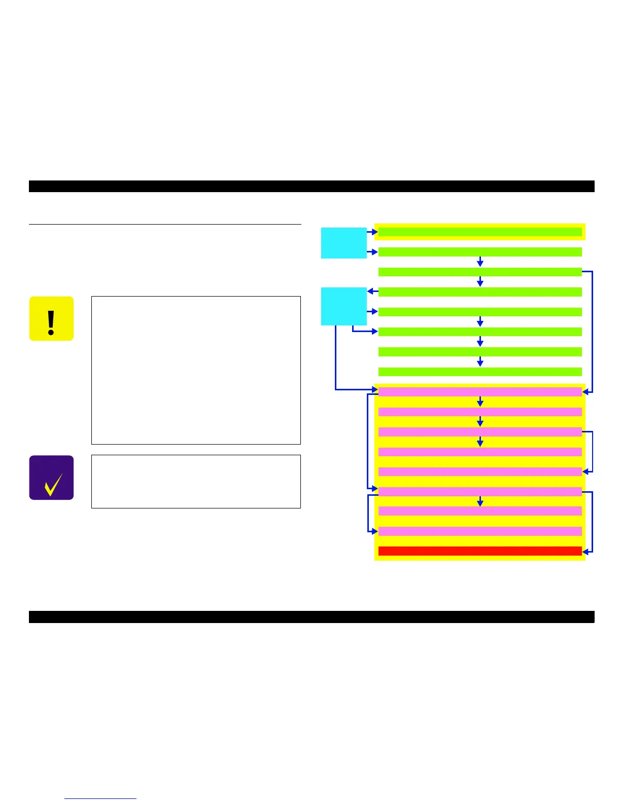
each main assembly of the GT-30000. The flow chart in "Figure 4-1.
Disassembly Procedure for GT-30000" indicates the various steps involved in
disassembly. When disassembling each assembly, you should refer to the
page numbers indicated in this figure.
Figure 4-1. Disassembly Procedure for GT-30000
C A U T I O N
!
The procedure steps which are enclosed in a
yellow box in "Figure 4-1. Disassembly Procedure
for GT-30000" are steps which require the use of a
special tool as part of the procedure. Make sure
that you read and fully understand the details
given in the relevant section of the procedure
before carrying out the disassembly operation.
!
The procedure steps which are enclosed in a red
box in "Figure 4-1. Disassembly Procedure for GT-
30000" are steps where adjustment is required
when re-assembling the relevant assembly after
disassembly. Make sure that you read and fully
understand the details given in the relevant
section of the procedure before making the
required adjustment.
C H E C K
P O I N T
Refer to A3 Auto Document Feeders service manual
for detail
s on the disassembly procedures for the
ADF.
Scanner
Mechanism
Disassembly
(See
Chapter 4.2.2)
Scanner Body
Disassembly
(See
Chapter 4.2.1)
Main Circuit Board Removal (See Chapter 4.2.1.2)
ADF Removal (See Chapter 4.2.1.1)
Mechanism Cover Removal (See Chapter 4.2.1.3)
Power Supply assembly Removal (See Chapter 4.2.2.1)
Cooling Fan Removal (See Chapter 4.2.2.2)
Power Supply Circuit Board Removal (See Chapter 4.2.2.3)
Panel Circuit Board Removal (See Chapter 4.2.2.6)
Lamp and Inverter Circuit Board Removal (See Chapter 4.2.2.7)
Lamp Cover Removal (See Chapter 4.2.2.7.1)
Lamp Removal (See Chapter 4.2.2.7.2)
Inverter Circuit Board Removal (See Chapter 4.2.2.7.3)
Relay Circuit Board Removal (See Chapter 4.2.2.11)
Document Size Sensor Removal (See Chapter 4.2.2.10)
CR Motor Assembly Removal (See Chapter 4.2.2.9)
Scanner Mechanism Removal (See Chapter 4.2.1.4)
Mechanism internal cover removal Removal (See Chapter 4.2.2.8)
Glass Frame Assembly Removal (See Chapter 4.2.2.5)
 Loading...


