A3 Size Color Flat Bed Scanner GT-30000 Revision A
DISASSEMBLY & ASSEMBLY Disassembly Procedures 49
4.2.2.5 Glass Frame Assembly Removal
1. Remove the mechanism cover. ("Chapter 4.2.1.3 Mechanism Cover
Removal".)
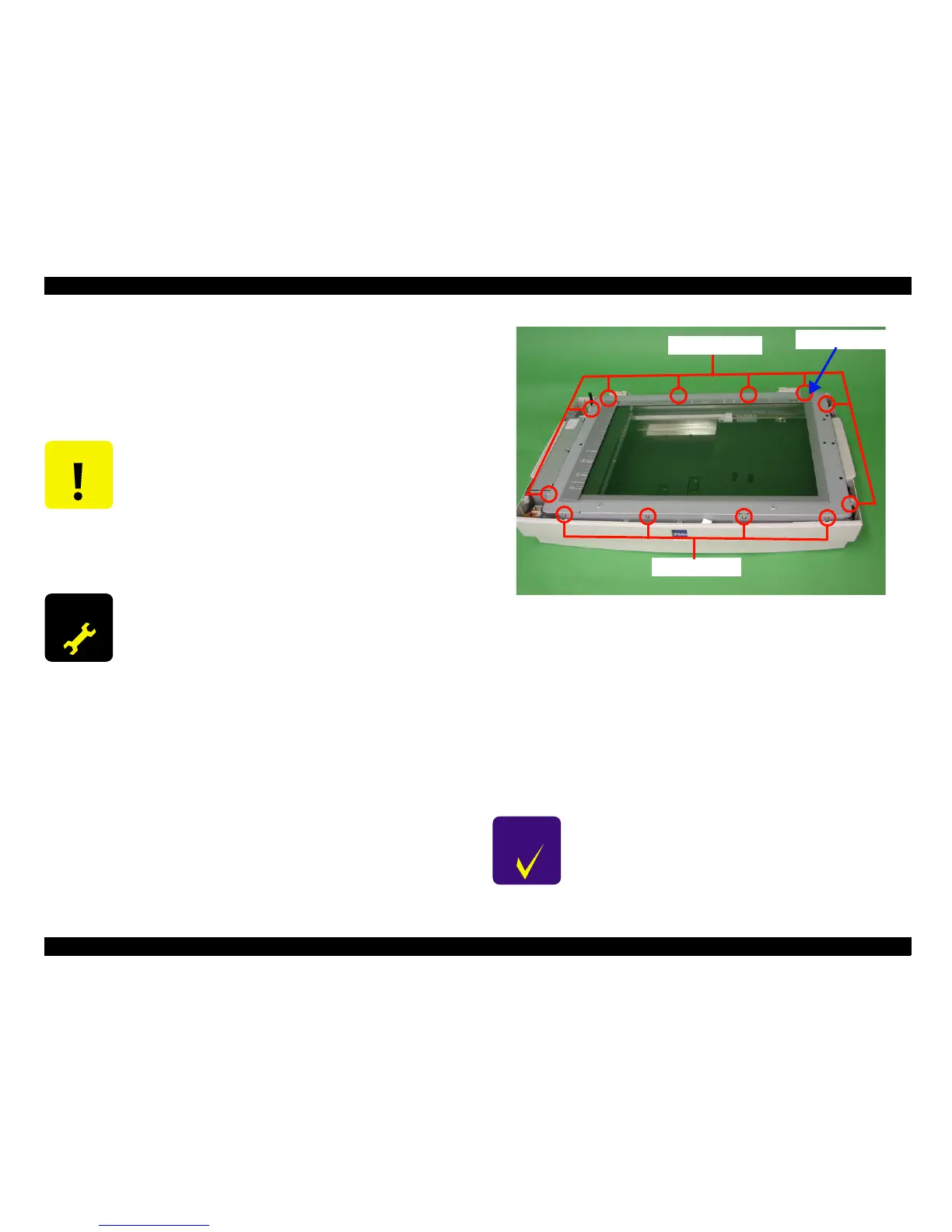
2. Remove the 12 screws (No.5), and then remove the glass frame assembly.
("Figure 4-15. Glass Frame Assembly Removal".)
Figure 4-15. Glass Frame Assembly Removal
4.2.2.5.1 Glass Frame Assembly Installation
After the glass frame assembly has been removed, be sure to follow the
procedure given below when re-installing the glass frame assembly.
1. Provisionally place the glass frame assembly on top of the scanner
mechanism in the position specified.
2. Determine the installation position while referring to "Figure 4-16. Glass
Frame Assembly Positioning".
3. Once the glass frame assembly installation position has been determined,
secure it in place by tightening the 12 screws.
C A U T I O N
!
Place the scanner on a stable, level surface when
removing the glass frame assembly.
!
When re-installing the glass frame assembly, be sure
to check the installation position thoroughly while
referring to "Chapter 4.2.2.5.1 Glass Frame Assembly
Installation". (If the glass frame assembly is not
installed in the correct position, the document
scanning start position will not be correct.)
A D J U S T M E N T
R E Q U I R E D
After re-installing or replacing the glass frame assembly,
be sure to adjust the home position of the scanner, by
using the special software. (See "Chapter 5.3.4 Home
Position Adjustment".)
C H E C K
P O I N T
When installing the glass frame assembly, the glass
fixing plate should be installed correctly. (See "Figure
4-16. Glass Frame Assembly Positioning".)
Screws
ScrewsScrews
Screws(No.
(No.(No.
(No.
5
)
))
)
Glass fixing plate
Screws
ScrewsScrews
Screws(No.
(No.(No.
(No.
5
)
))
)
 Loading...


