A3 Size Color Flat Bed Scanner GT-30000 Revision A
DISASSEMBLY & ASSEMBLY Disassembly Procedures 54
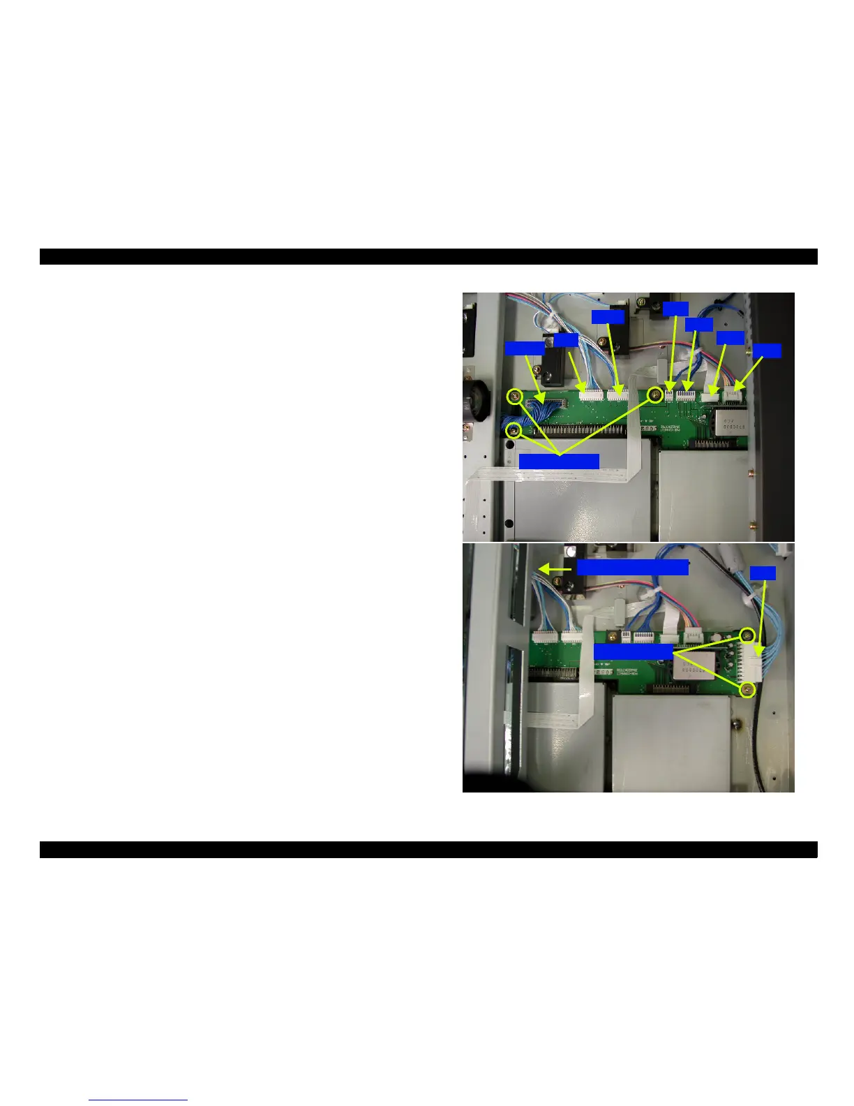
4.2.2.11 Relay Circuit Board Removal
1. Remove the main circuit board assembly. (See "Chapter 4.2.1.2 Main
Circuit Board Removal".)
2. Remove the circuit board and sensor cover. (See "Chapter 4.2.2.8
Mechanism internal cover removal Removal".)
3. Remove the five screws (No.8) which are securing the relay circuit board to
the scanner chassis, and then disconnect all connectors (CN1,
CN3~CN10, CN13) from the relay circuit board.
4. Lift the relay circuit board up to remove it. (See "Figure 4-23. Relay Circuit
Board Removal".)
Figure 4-23. Relay Circuit Board Removal
Screws (No.8)
CN13
CN9
CN4
CN6
CN1
CN3
Carriage movement
Screws (No.8)
CN10
CN5
 Loading...


