A3 Size Color Flat Bed Scanner GT-30000 Revision A
DISASSEMBLY & ASSEMBLY Disassembly Procedures 43
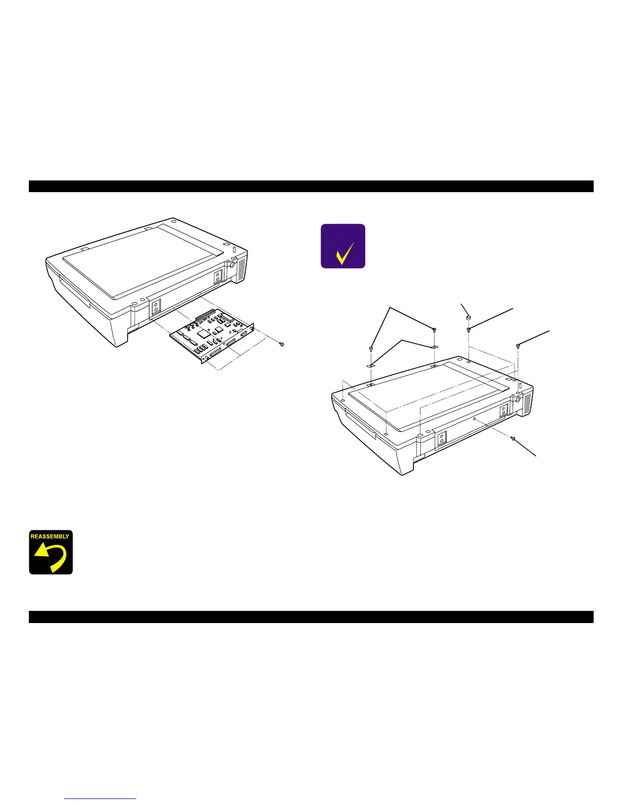
Figure 4-3. Main Circuit Board Assembly Removal
4.2.1.3 Mechanism Cover Removal
1. Remove the document cover. (See "Figure 4-2. ADF Removal".)
2. Remove the four screw caps. (See "Figure 4-5. Cap Removal".)
3. Remove the nine screws (No.1: 4, No.2: 2, No.3: 2 and No.4: 1) which are
securing the mechanism cover to the scanner chassis. (See "Figure 4-4.
Mechanism Cover Removal".)
4. Lift the mechanism cover and plate up to remove them. (See "Figure 4-4.
Mechanism Cover Removal".)
Figure 4-4. Mechanism Cover Removal
When installing, the magnetic catch screw tightening
torque is 100±10 N
•
cm.
C H E C K
P O I N T
When re-installing the mechanism cover, the magnetic
catch should be installed in the specified position. (See
"Figure 4-4. Mechanism Cover Removal".)
Screws (No.2)
Screws (No.3)
Screws (No.1)
Screw Caps
Screws (No.4)
Magnetic
Catch
 Loading...


