A3 Size Color Flat Bed Scanner GT-30000 Revision A
DISASSEMBLY & ASSEMBLY Overview 38
4.1 Overview
This chapter describes the procedures for disassembling and assembling the
main components of the scanner GT-30000. (Refer to A3 Auto Document
Feeders service manual for detail on the disassembly and assembly
procedures for the ADF.)
Except where indicated separately, all procedures for re-assembling the
disassembled assemblies and components should be carried out by following
the disassembly procedures in reverse.
Sections which may result in injury or risk to life if proper care is not taken are
indicated by a WARNING symbol.
Sections where particular care should be taken beforehand during disassembly
or assembly are indicated by a CAUTION symbol.
Tips designed to assist with disassembly are indicated by a CHECK POINT
symbol.
If the assembly procedure differs from the reverse of the disassembly
procedure, the steps which are different are indicated by a RE-ASSEMBLY
symbol.
Furthermore, if adjustment is required as a result of disassembly, the
adjustment steps are indicated by an ADJUSTMENT symbol.
If disassembly of assemblies or components which are not mentioned in this
chapter are required, please refer to the separate general disassembly
diagram.
Be sure to read the Points to Note on the next page before starting any
disassembly procedures.
4.1.1 Points to Note
Make sure that you read and understand the following warnings and cautions
before disassembling or re-assembling any of the components of the EPSON
GT-30000.
W A R N I N G
!
Be sure to disconnect the power cable from the AC
power socket prior to servicing.
!
Be sure to wear gloves when disassembling or
assembling any parts of the scanner in order to avoid
injury from cuts.
!
Be careful to avoid static electric discharges when
touching internal components, in order to protect the
microprocessor and other circuits.
!
Since this scanner weighs heavy (approximately
30kg), it must be taken care when working.
C A U T I O N
!
Use only the recommended tools when carrying out
disassembly, assembly and adjustments.
!
Observe the specified torque when tightening
screws. ("Table 4-1 List of Screw Tightening
Torques")
!
The specified adjustments should be carried out
after disassembling the scanner.
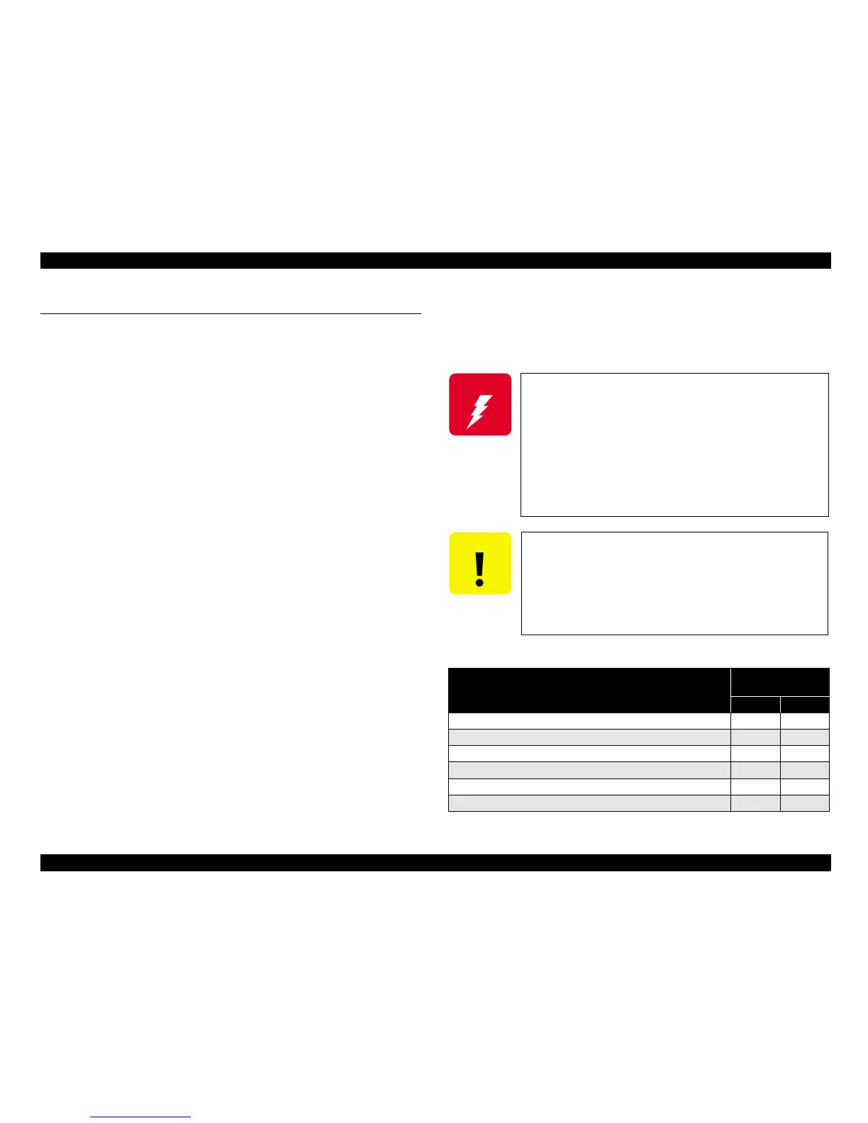
Table 4-1. List of Screw Tightening Torques
Screw tightening location
Screw tightening
torque
(
((
(N
NN
N•
••
•cm
cmcm
cm)
))
)
M3 M4
When securing two panels together
100±20 160±20
When securing a molding to a panel
60±10 100±10
When securing a circuit board to a panel
40±10 60±10
When securing to a molding using a molding tapping screw
50±10 70±10
When securing the ADF magnetic catch
‑100±10
When securing a handle
50±10 ‑
 Loading...


