A3 Size Color Flat Bed Scanner GT-30000 Revision A
DISASSEMBLY & ASSEMBLY Disassembly Procedures 50
Figure 4-16. Glass Frame Assembly Positioning
4.2.2.6 Panel Circuit Board Removal
1. Remove the mechanism cover. ("Chapter 4.2.1.3 Mechanism Cover
Removal".)
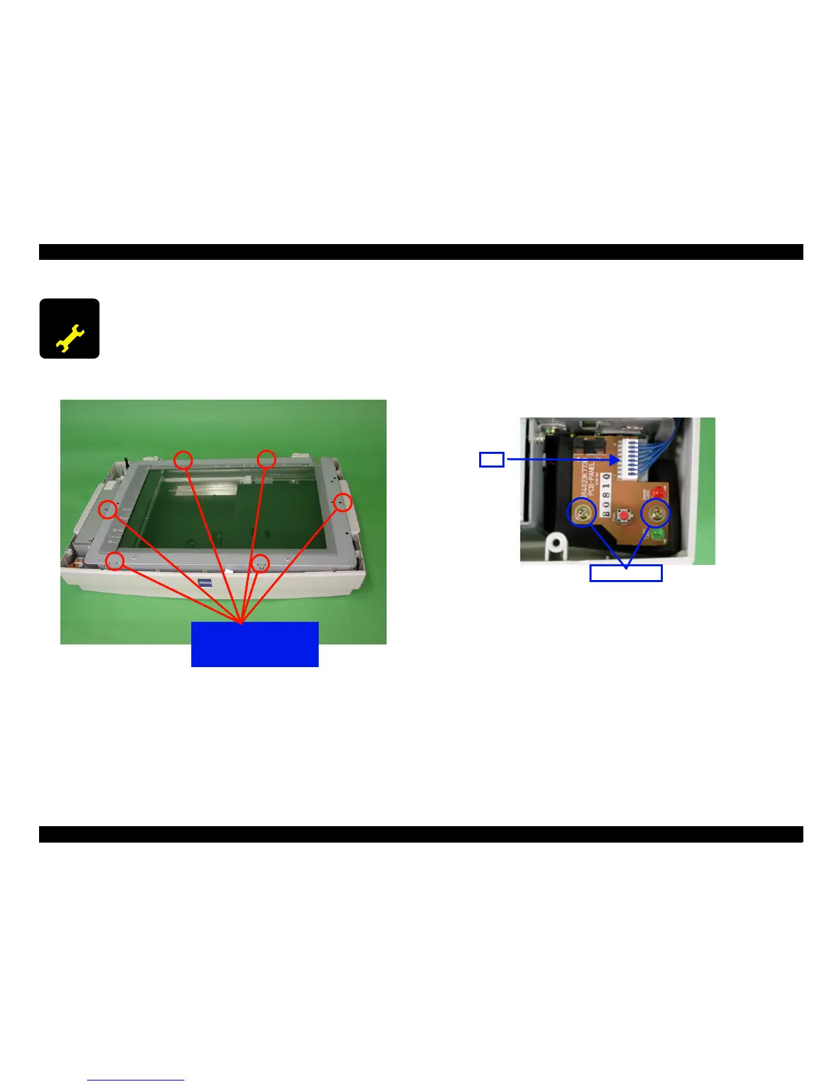
2. Disconnect connector CN1 from the panel circuit board.
3. Remove the two screws (No.8) which are securing the panel circuit board,
and then remove the board. (See "Figure 4-17. Panel Circuit Board
Removal".)
Figure 4-17. Panel Circuit Board Removal
4.2.2.7 Lamp and Inverter Circuit Board Removal
This section describes the procedures for removing the lamp and inverter
circuit board from the carriage.
A D J U S T M E N T
R E Q U I R E D
Once the glass frame assembly has bee removed, you
must use calibration software to adjust the glass frame
assembly after it is re-installed. (See "Chapter 5.3.4 Home
Position Adjustment".)
Align the glass frame
assembly groove with
the mechanism tabs.
Screws
ScrewsScrews
Screws(No.
(No.(No.
(No.
8
)
))
)
CN1
CN1CN1
CN1
 Loading...


