A3 Size Color Flat Bed Scanner GT-30000 Revision A
DISASSEMBLY & ASSEMBLY Disassembly Procedures 42
4.2.1 Scanner Body Disassembly
This section describes procedures for disassembling the major units of the
scanner.
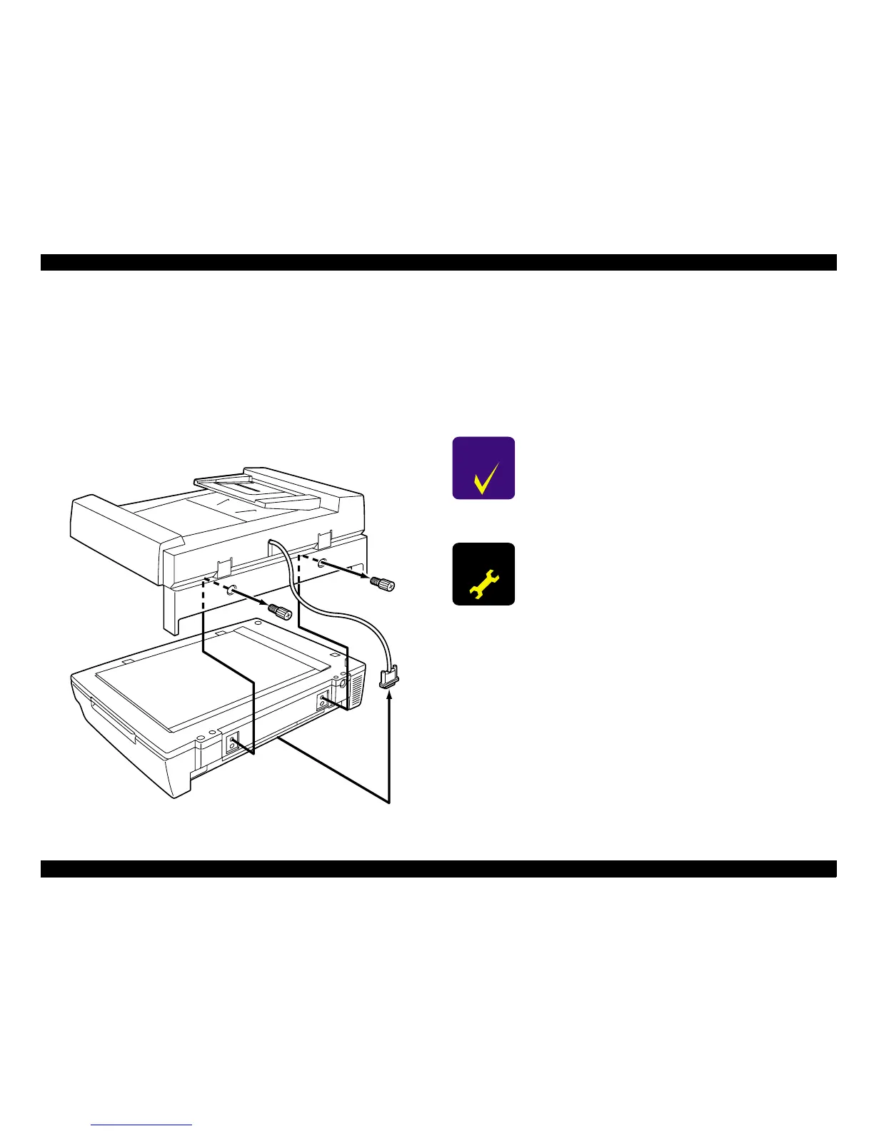
4.2.1.1 ADF Removal
1. Disconnect the power supply cable and the ADF connection cable from the
scanner.
2. Remove the two screws which are securing the ADF to the rear of the
scanner, and then remove the ADF. (Refer to A3 Auto Document Feeders
service manual for detail.)
Figure 4-2. ADF Removal
4.2.1.2 Main Circuit Board Removal
The main circuit board (PBA-MAIN) of this scanner consists of an independent
main circuit board assembly. The main circuit board assembly is designed so
that it can be easily removed from the scanner.
1. Remove the three screws (No.6) which are securing the main circuit board
assembly at the rear of the scanner, and then remove the main circuit
board assembly from the scanner.(See "Figure 4-3. Main Circuit Board
Assembly Removal".)
C H E C K
P O I N T
The main circuit board assembly can be removed
easily by pulling the two card spacers at the left and
right sides of the assembly.
A D J U S T M E N T
R E Q U I R E D
After replacing the main circuit board, you must set the
product name, paper detect size and confirm the Home
Position of the scanner, by using the special software.
(See "Chapter 5.3.3 Using the Name Rewriting Software".)
 Loading...


