A3 Size Color Flat Bed Scanner GT-30000 Revision A
ADJUSTMENTS Adjustments Using the Special Software 64
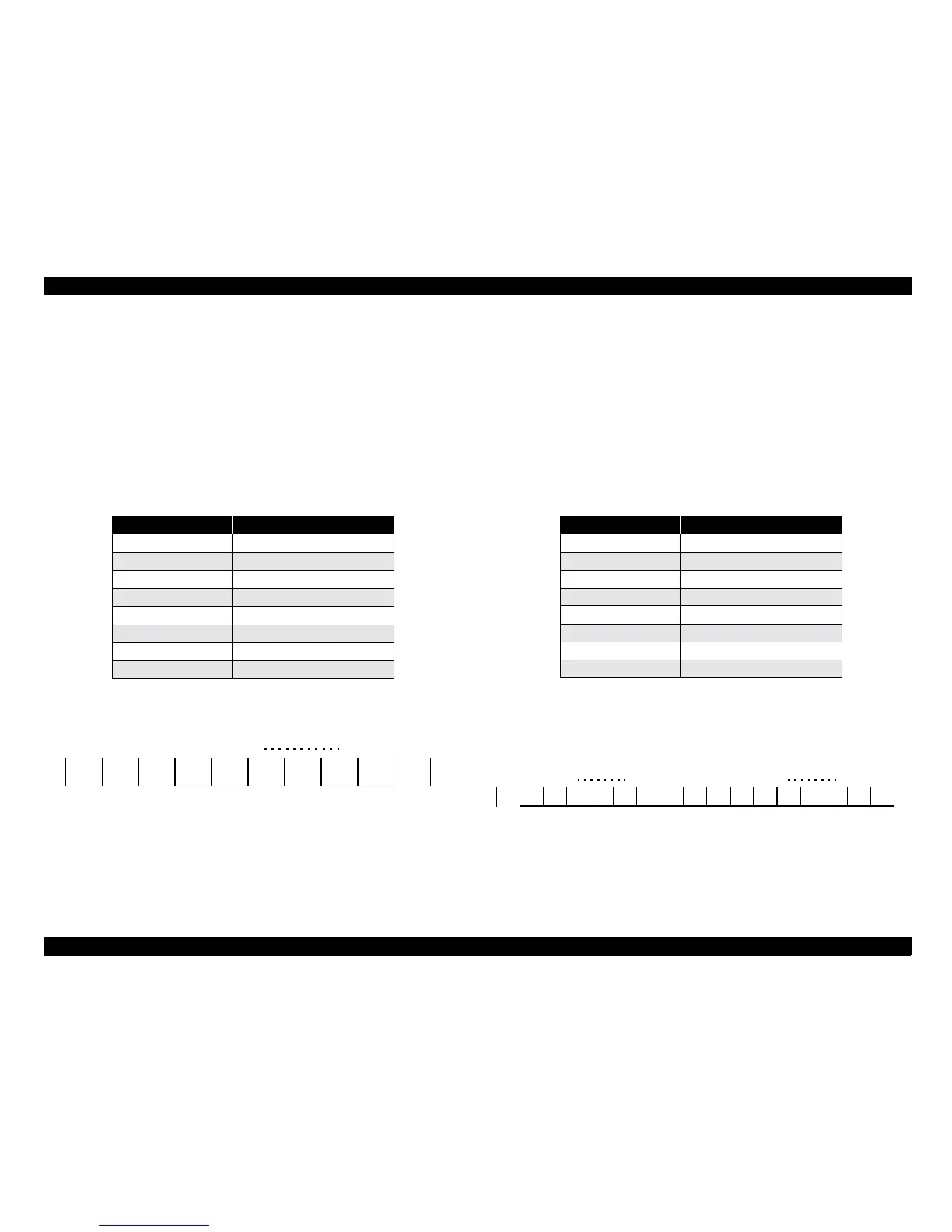
5.3.4.2 Main Scanning Correction Value Adjustment
1. Click the Read button to read the scanner information.
2. Enter a value which is greater or less than the current value by a multiple of
4 (the adjustment unit is 4 pixels [approx. 0.17 mm]).
!
If overrun has occurred, increase the value.
!
If the ruler part has been truncated by more than 1 mm, reduce the
value.
For details, see "Table 5-4 Main Scanning Direction Adjustment".
!
The valid range of data that can be entered is within the range of 0 to
84. (See "Table 5-9 Main Scanning Direction Adjustment Range".)
Figure 5-9. Main Scanning Direction Adjustment Range
5.3.4.3 Sub Scanning Correction Value Adjustment
1. Click the Read button to read the scanner information.
2. Enter a value which is greater or less than the current value by a multiple of
8 (the adjustment unit is 2 pixels [approx. 0.1 mm]).
!
If overrun has occurred, increase the value.
!
If the ruler part has been truncated by more than 1 mm, reduce the
value.
For details, see "Table 5-5 Sub Scanning Direction Adjustment".
!
The valid range of data that can be entered is within the range of 248
to 128 and 0 to 120. (See "Table 5-10 Sub Scanning Direction
Adjustment Range".)
Figure 5-10. Sub Scanning Direction Adjustment Range
Table 5-4. Main Scanning Direction Adjustment
Pixels adjusted Variation factor
1^4 4
5^8 8
9 ^12 12
• •
••
21^24 24
••
• •
0 4 8 12 16 76 80 84
Table 5-5. Sub Scanning Direction Adjustment
Pixels adjusted Variation factor
1 or 2 8
3 or 4 16
5 or 6 24
• •
••
11 or 12 48
••
• •
248 240 232 144 136
0
or
128 8 16 24 32 106 112 120
0
or
128
 Loading...


