A3 Size Color Flat Bed Scanner GT-30000 Revision A
ADJUSTMENTS Adjustments Using the Special Software 63
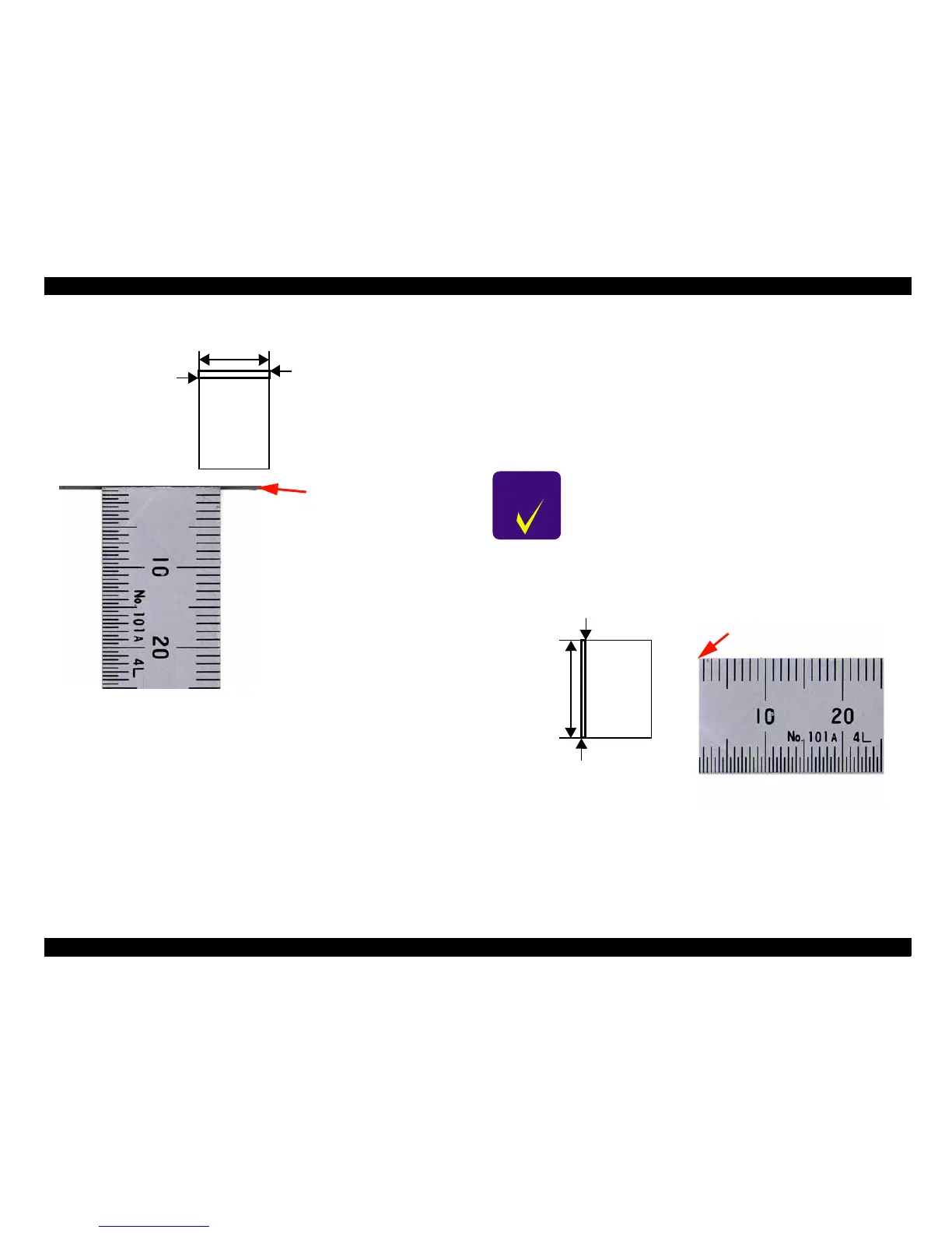
Figure 5-7. Checking the Main Scanning Correction Value
4. Enlarge the scanned image on the screen to check the image. If the edge
panels are included in the image, or if the ruler part of the scanned image
is truncated by more than 1 mm, adjust the main scanning correction
value. (See "Chapter 5.3.4.2 Main Scanning Correction Value
Adjustment".)
5.3.4.1.2 Check the home position in the sub scanning direction
1. Place a sheet of white paper (one sheet of A3 paper or two sheets of A4
paper) and a ruler onto the document platen so that they are against the
main scanning edge panel.
2. Set the scanning area in the preview screen. (See "Figure 5-8. Checking
the Sub Scanning Correction Value".
3. Scan the image at 600 dpi and as a 24-bit color image.
Figure 5-8. Checking the Sub Scanning Correction Value
4. Enlarge the scanned image on the screen to check the image. If the edge
panels are included in the image, or if the ruler part of the scanned image
is truncated by more than 1 mm, adjust the sub scanning correction value.
(See "Chapter 5.3.4.3 Sub Scanning Correction Value Adjustment".)
Set the maximum area
Set so that there is no gap
About 2~3 cm
Ruler part of scanned image
[Example]
Edge panel is included
in the scan (adjustment
required).
C H E C K
P O I N T
Use the Imaging software which is bundled with Windows
95/98 as the scanning application.
Set the
maximum
area
Set so that there is no gap
About 2~3 cm
Ruler part of scanned image
[Example]
Ruler part of the scanned
image is truncated by more
than 1 mm (adjustment
required).
 Loading...


