A3 Size Color Flat Bed Scanner GT-30000 Revision A
TROUBLESHOOTING Overview 33
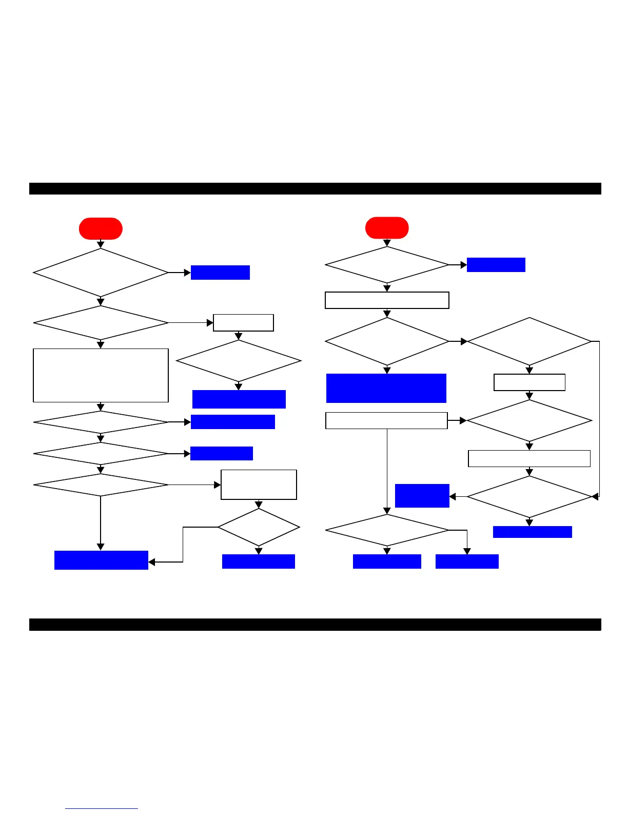
Flowchart 3-1. READY LED does not light up
Flowchart 3-2. CR (Mirror/lamp) does not move
Start
Has the power
supply fuse blown?
Are the main circuit
board and connection
circuit board connected
incorrectly?
Is the output incorrect?
Remove the main circuit board and check
that the following voltages are present at
connector CN5 of the connect circuit board.
Between Pins:
10 and 9: +24 V 6 and 5: +5 V
8 and 7: +12 V 4 and 3: +3.3 V
Replace the main, connection
and CCD circuit boards.
Does the motor operate?
Does the indicator light?
Connect properly.
No
No
No
Yes
Yes
Yes
Replace the power supply.
Yes
Replace the motor.
Yes
Yes
Yes
Check the fuse
Has the power
supply fuse
blown?
Yes
Replace the main and
connection circuit boards.
Does the
indicator
light?
Carry out the indicator
test in test mode.
Replace the indicator.
No
Yes
To Troubleshooting for power supply
board (See "Chapter 3.1.3.1 Power
Supply Board (PWS-POWER Board)".)
Start
Transportation
screw set to
locked position?
Turn on the scanner.
Is +24 DC present
between pins 10 and 9
(GND) of connection
circuit board connector
CN5?
Is +24 DC present
between pins 1 and 2-
PGND of connection
circuit board connector
CN3?
Unlock the screw
Yes
Turn on the scanner.
Turn off the scanner
and manually move
the carriage.
Disconnect connect i on ci rcui t boar d connect or CN3.
Disconnect connect ion ci rcui t board connector CN3.
Turn off the
scanner and
manually move
the carriage.
The mechanism
is defective.
Replace it
Replace PBA-CONNECT
Is the motor coil
resistance at the
specified value?
Replace the motorReplace PBA-MAIN
No
No
Yes
Yes
No
No
No
Yes
No
No
 Loading...


