A3 Size Color Flat Bed Scanner GT-30000 Revision A
OPERATING PRINCIPLES Electrical Circuit Operations 27
PBA-MAIN BOARD
PBA-ISN BOARD
PBA-CONNECT BOARD
This relay board connects the PBA-MAIN board with the PBA-ISN, PBA-
PANEL, PWS-POWER, PBA-LAMP boards and mechanism.
PBA-PANEL BOARD
This board has a power switch (push-lock), start switch and LED indicators
(READY, ERROR).
PWS-POWER BOARD
Since the power supply circuit board PWS-POWER for this scanner meets the
universal specification requirements, it can be used with rated voltage from
100V to 240V AC.
NOTE: 1) Power on current: 25 A (O-Peak) or less. However, maximum
input should be 264 V AC or less.
2) Leakage current: 0.25 mA or less
(110 V AC, 50 Hz, maximum load)
3.5 mA or less
(140 V AC, 60 Hz, maximum load)
3.5 mA or less
(264 V AC, 60 Hz, maximum load)
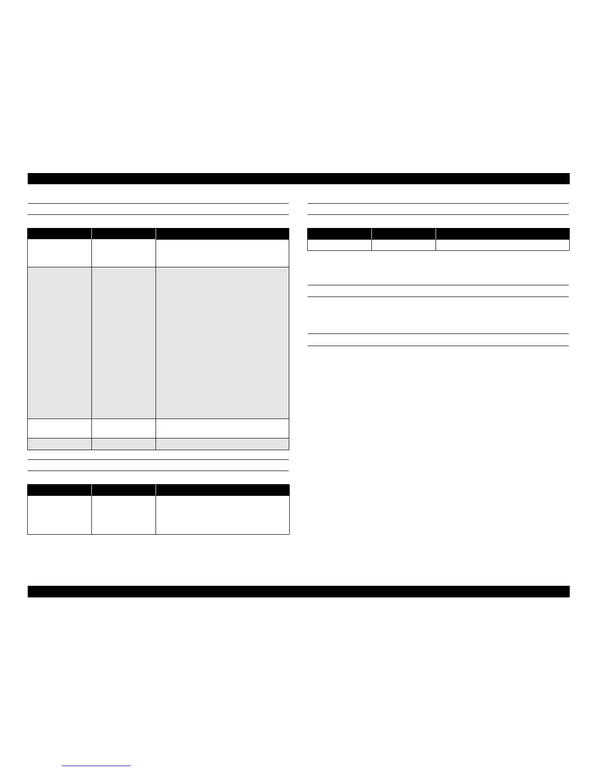
Table 2-1.
Name Location Description
CPU
HD6412352F20
IC1
The CPU that controls this entire operation
of this board and operates at 20 MHz.
Voltage = 5.0V
ASIC
µ
PU 65949 SI-079-F6
IC2
The image processor that controls the
functions and operating described below:.
Operating frequency
External: 48 MHz
Internal: 120 MHz
(CCD driver assembly)
30 MHz
(other than CCD driver
assembly)
Voltage:
3.3V
Control functions
CCD control
Line correction processing
Buffer memory
Image processing
MB86606 IC3
The SCSI interface processor operates at
40MHz. Voltage = 5.0V.
BH9595FP-Y IC30/31 Terminator control
Table 2-2.
Name Location Description
CCD sensor
µ
PD3728D
IC9
Color CCD line sensor outline:
Effective pixel = 7020 pixels x 3 colors
Bi-D scanning rate =
Max. 10 million pixels/second
Table 2-3.
Name Location Description
STK672-080 IC1 Motor drive control
 Loading...


