A3 Size Color Flat Bed Scanner GT-30000 Revision A
APPENDIX Connector Pin Assignment 71
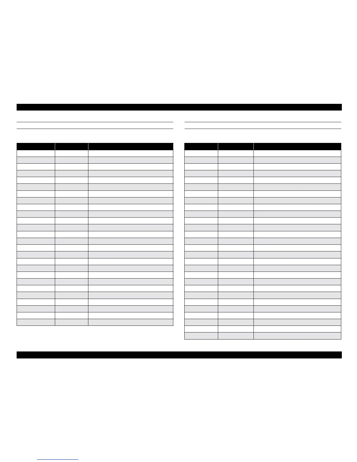
PBA-MAIN - ADF I/F (CN4) PBA-MAIN - PBA-CONNECT (CN5)
Table 7-4.
PIN No. Signal Name Function
1 OP1 ADF detection
2 OP2 ADF detection
3 N.C. Not used
4 N.C. Not used
5 N.C. Not used
6 +5V Power supply (+5V)
7GND ADF GND
8 +24V Power supply (+24V)
9 N.C. Not used
10 N.C. Not used
11 N.C. Not used
12 N.C. Not used
13 +5V Power supply (+5V)
14 GND ADF GND
15 +24V Power supply (+24V)
16 +24V Power supply (+24V)
17 GND ADF GND
18 +5V Power supply (+5V)
19 +5V Power supply (+5V)
20 +24V Power supply (+24V)
21 RXD ADF data reception
22 *RXD ADF data reception
23 TXD ADF data transmission
24 *TXD ADF data transmission
25 DSR ADF data reception
26 DTR ADF data transmission
Table 7-5.
PIN No. Signal Name Function
1 +24V Power supply (+24V)
2 +24V Power supply (+24V)
3 PGND Power supply GND
4 PGND Power supply GND
5 PGND Power supply GND
6 PGND Power supply GND
7 SGND Signal GND
8 ENSON Energy Star mode control
9 SGND Signal GND
10 /DREXT Expansion I/F control
11 /SYSRES Expansion I/F control
12 SGND Signal GND
13 D6 Expansion I/F data bus
14 D4 Expansion I/F data bus
15 D2 Expansion I/F data bus
16 D0 Expansion I/F data bus
17 SGND Signal GND
18 /WR Expansion I/F control
19 /CS Expansion I/F control
20 /DAIF Expansion I/F control
21 SGND Signal GND
22 DM14 Expansion I/F data bus
23 DM12 Expansion I/F data bus
24 DM10 Expansion I/F data bus
25 DM8 Expansion I/F data bus
26 SGND Signal GND
27 DM6 Expansion I/F data bus
28 DM4 Expansion I/F data bus
 Loading...


