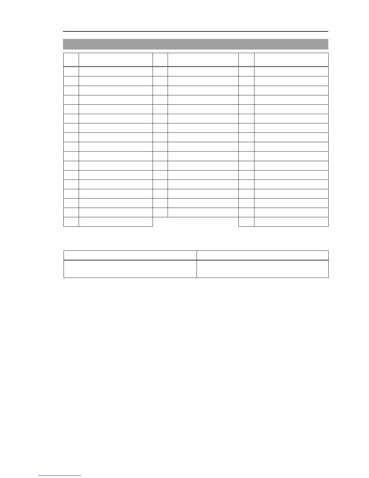
Signal Name
1 Input common No. 0 to 7 18 Input common No. 8 to 15 34 Input common No. 16 to 23
2 Input No. 0 (Start) 19 Input No. 8 35 Input No. 16
3 Input No. 1 (SelProg1) 20 Input No. 9 36 Input No. 17
4 Input No. 2 (SelProg2) 21 Input No. 10 37 Input No. 18
5 Input No. 3 (SelProg4) 22 Input No. 11 38 Input No. 19
6 Input No. 4 (Stop) 23 Input No. 12 39 Input No. 20
7 Input No. 5 (Pause) 24 Input No. 13 40 Input No. 21
8 Input No. 6 (Continue) 25 Input No. 14 41 Input No. 22
9 Input No. 7 (Reset) 26 Input No. 15 42 Input No. 23
10 Output No. 0 (Ready) 27 Output No. 6 (SError) 43 Output No.11
11 Output No. 1 (Running) 28 Output No. 7 (Warning) 44 Output No.12
12 Output No. 2 (Paused) 29 Output No. 8 45 Output No.13
13 Output No. 3 (Error) 30 Output No. 9 46 Output No.14
14 Output No. 4 (EstopOn) 31 Output No.10 47 Output No.15
15 Output No. 5 (SafeguardOn) 32 NC 48 NC
16 NC 33 Output common No. 8 to 15 49 NC
17 Output common No. 0 to 7 50 NC
Remote function inside ( ) in the table above is initially assigned to both input and output from 0 to 7. For
further details, refer to 12. I/O Remote Settings.
Connector Standard
I/O Connector (Controller side)
Mounting style #4 - 40
* The I/O connector, I/O cable, and terminal block are offered as options.
* I/O connector is included with shipment.
RC90 (EPSON RC+ 7.0) Rev.4 57