2.2 Functions
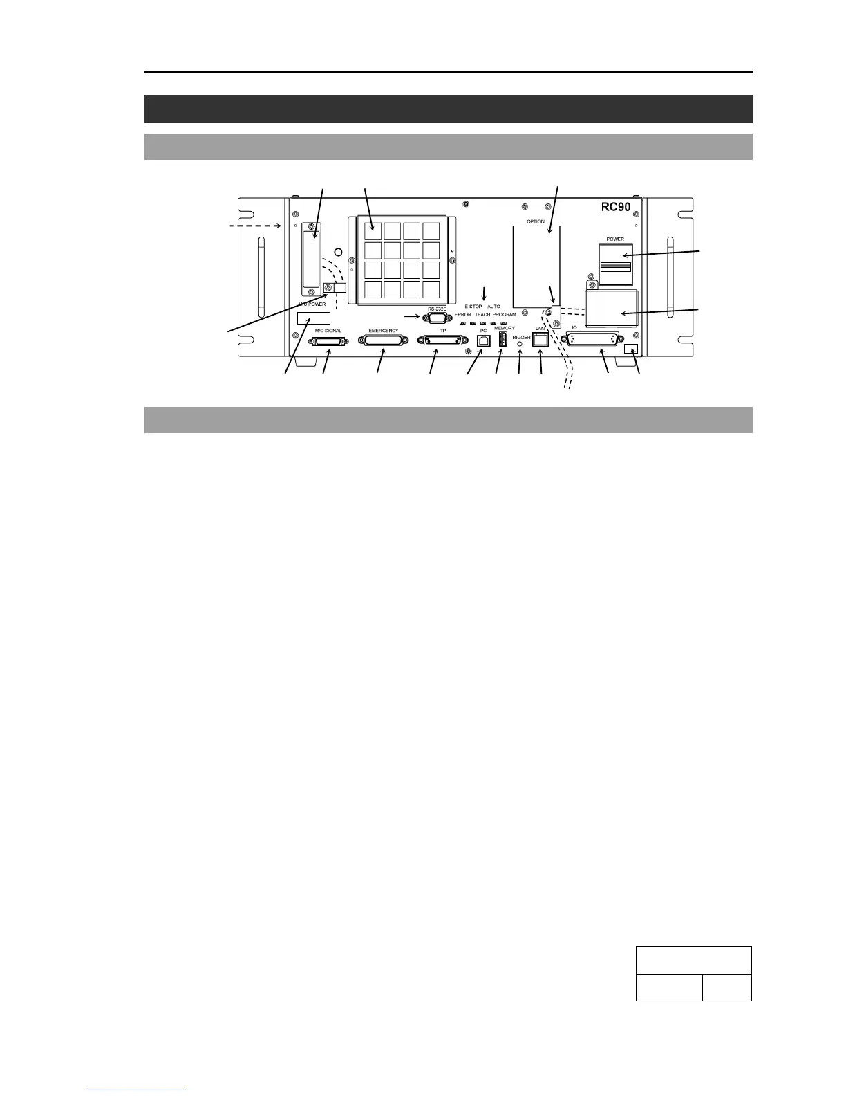
(1) POWER switch
Turns ON or OFF the Controller.
(2) AC IN
The terminal block for 200VAC power input.
For details, refer to Setup & Operation 3.3.2 AC Power Cable.
(3) LED
The LED indicates current operation mode (ERROR, E-STOP, TEACH, AUTO, or
PROGRAM mode). For details, refer to Setup & Operation 2.3 LED.
(4) Fan Filter
A protective filter is installed in front of the fan to filter out dust.
Check the condition of the filter regularly and clean it when necessary. A dirty
filter may result in malfunction of the robot system due to temperature rise of the
Controller.
(5) Signature label
The serial number of the Controller and other information are shown.
(6) MT label
The label indicates the specification number of the customized manipulator or
controller. If this label is attached to your manipulator or controller, it may require
a specific maintenance procedure. In this case, make sure to contact your dealer
before performing any maintenance procedures.
(7) Controller Number label
The serial number of the Controller is indicated.
(8) Connection Check label

 Loading...


