Setup & Operation 2. Part Names and Functions
(19) Option slot
Option boards such as expansion I/O board, Fieldbus I/O board, RS-232C board, PG
board can be installed. Two slots are available.
For details, refer to Setup & Operation 13.Option Slots.
(20) Cable Clamp
This can be used to secure the M/C Power Cable and the AC Power cable.
(21) Battery (Mounted inside the controller)
This is a lithium battery for data backup.
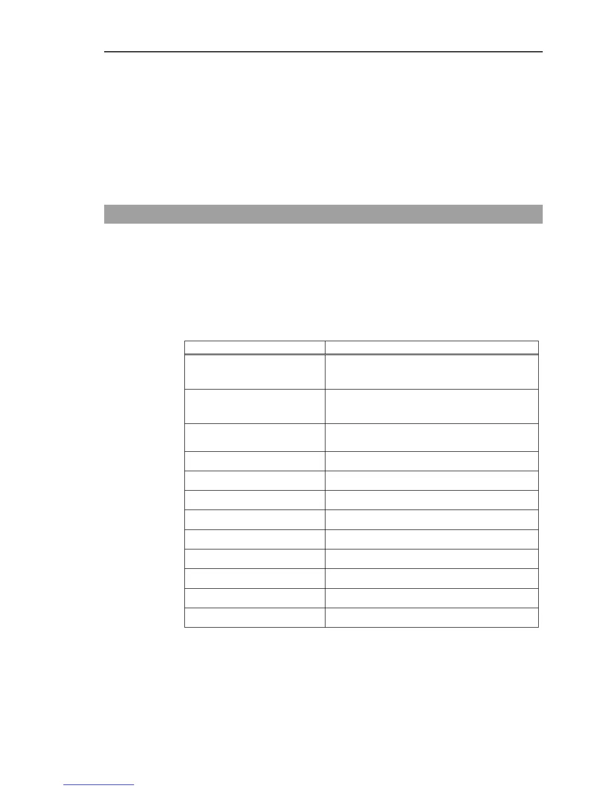
2.3 LED
Five LEDs are located on the front panel of the Controller.
LEDs (ERROR, E-STOP, TEACH, AUTO, PROGRAM) turn ON according to the
controller status (error, Emergency Stop, TEACH mode, Auto mode, Program mode).
From turning ON the Controller to completing startup
Three LEDs (TEACH, AUTO, PROGRAM) blink.
After Controller Startup
TEACH AUTO, PROGRAM blink.
Complete Controller status
storage to USB memory
Failure of Controller status
storage to USB memory
ERROR, TEACH, AUTO, PROGRAM turn ON
(for 2 seconds).
Error ERROR turns ON
Warning ERROR blinks.
Emergency Stop E-STOP turns ON.
TEACH mode TEACH blinks.
Auto mode (AUTO mode) AUTO blinks.
Program mode (AUTO mode) PROGRAM blinks.
Recovery mode ERROR, TEACH, PROGRAM turn ON.
AC power supply drop TEACH, AUTO turn ON.
Test mode TEACH blinks.
RC90 (EPSON RC+ 7.0) Rev.4 15
 Loading...


