71 / 84
7 • Maintenance and servicing
80116-938_V24392
2023-03
Test set-up and test procedure
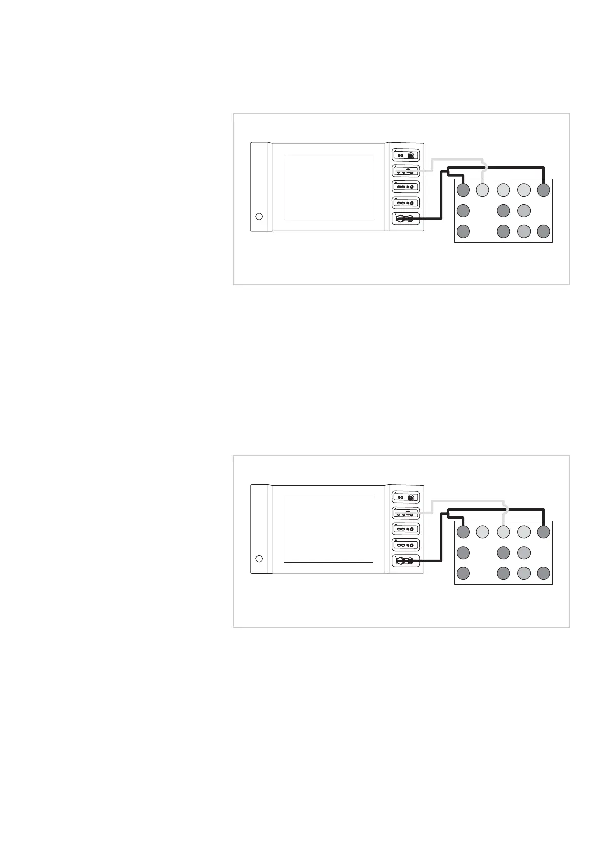
Asymmetry > 85 %
Fig. 7-5
• The test specimen is connected to the power supply via the power
cord.
• The NE socket of the test specimen is connected to the VIO Testbox via
the patient cable NE with the adapter cable.
• The AE socket of the test specimen is connected to the VIO test box via
the patient cable AE and the electrode handle with the laboratory
measuring cable.
1. Activate test specimen via COAG button on the electrode handle for
approx. 10 seconds. During the entire activation time there must be
no warning signal.
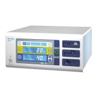
Asymmetry > 50 %
Fig. 7-6
• The test specimen is connected to the power supply via the power
cord.
• The NE socket of the test specimen is connected to the VIO Testbox via
the patient cable NE with the adapter cable.
• The AE socket of the test specimen is connected to the VIO test box via
the patient cable AE and the electrode handle with the laboratory
measuring cable.
1. Use the COAG button of the electrode handle to activate the test
specimen for approx. 10 seconds . A visual warning must appear
approx. 2 seconds after activation. The test specimen must not inter-
rupt activation in this case.
Testbox 20100-101
1
2
9
4 5
3
10
6
11
12
7
8
AE
NE
Testbox 20100-101
1
2
9
4 5
3
10
6
11
12
7
8
AE
NE