67 / 84
7 • Maintenance and servicing
80116-938_V24392
2023-03
Monitor circuits
Return electrode monitoring
system
Limit resistance
Testing and measuring equipment
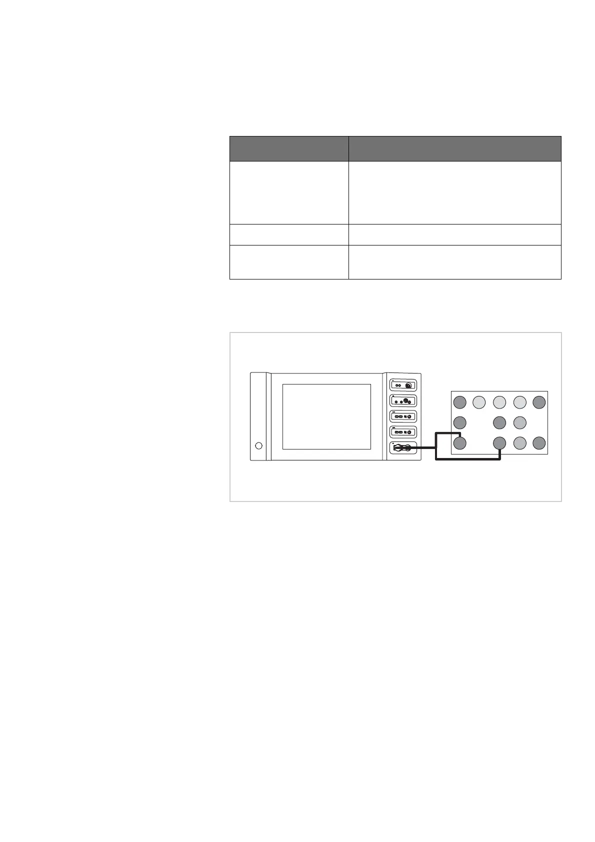
Test set-up and test procedure
133 Ohm ±10 Ohm
Fig. 7-3
• The test specimen is connected to the power supply via the power
cord.
• The return electrode socket is connected to the VIO test box using the
return electrode adapter cable via the return electrode patient cable.
Erbe Art. No. Description
20194-070 Patient cable NE
or
20194-075 Patient cable NE, international
20100-033 Adapter cable NE
20100-101 VIO Testbox Symmetry/Resistance (NE
asymmetry/critical resistance)
Testbox 20100-101
1
2
9
4 5
3
10
6
11
12
7
8