7 • Maintenance and servicing
76 / 84
80116-938_V24392
2023-03
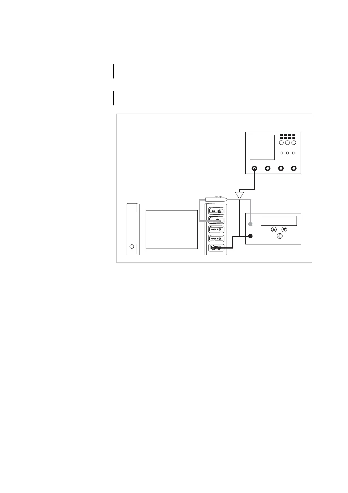
Test setup
Fig. 7-9
• The test specimen is connected to the power supply via the power
cord.
• The test setup is designed as shown in the illustration above.
ATTENTION! When connecting the probe to the input of the HF power meter, make
absolutely sure that minus is connected to the neutral electrode.
ATTENTION! Set the pulse-width modulation on the probe to 1000:1 to prevent the
probe from being damaged or the results from being distorted.
AE
NE
HF power meter
High Voltage
Differential probe
Oszilloscope