DIR911T User Guide
86
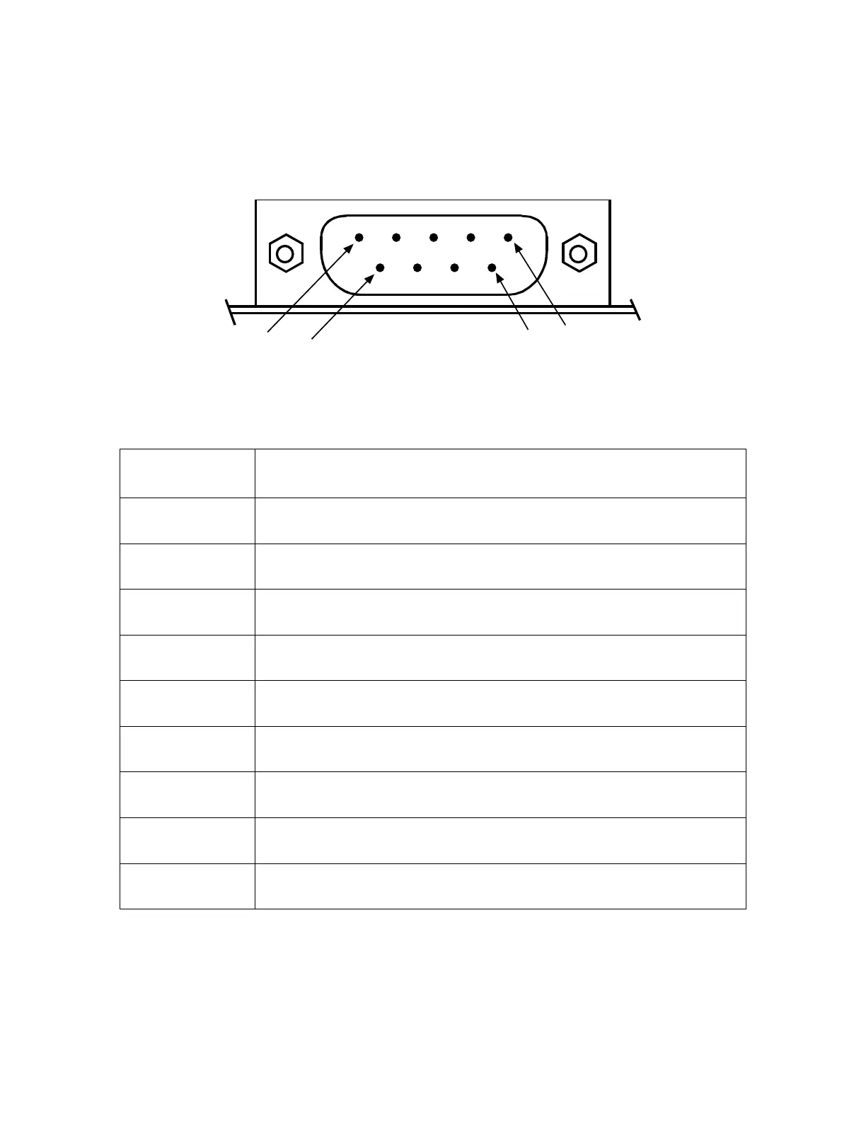
pin diagram for this connector is shown in Figure #72 and the pin description is shown in
Table #19.
1
6
5
9
Figure 72: Rear Panel External Activity DB-9 Connector Pin Diagram
Pin Description
1 Line #1 Active Input
2 Line #3 Active Input
3 Line #2 Activate Output
4 Line #3 Activate Output
5 Ground
6 Line #2 Active Input
7 Line #1 Activate Output
8 Line #4 Active Input
9 Line #4 Activate Output
Table 19: Rear Panel External Activity DB-9 Connector Pin Description