X1200 Series Router Manual
INSTALLATION
Revision 1.3.2
Page 2-1
2. INSTALLATION
2.1. REAR PANEL
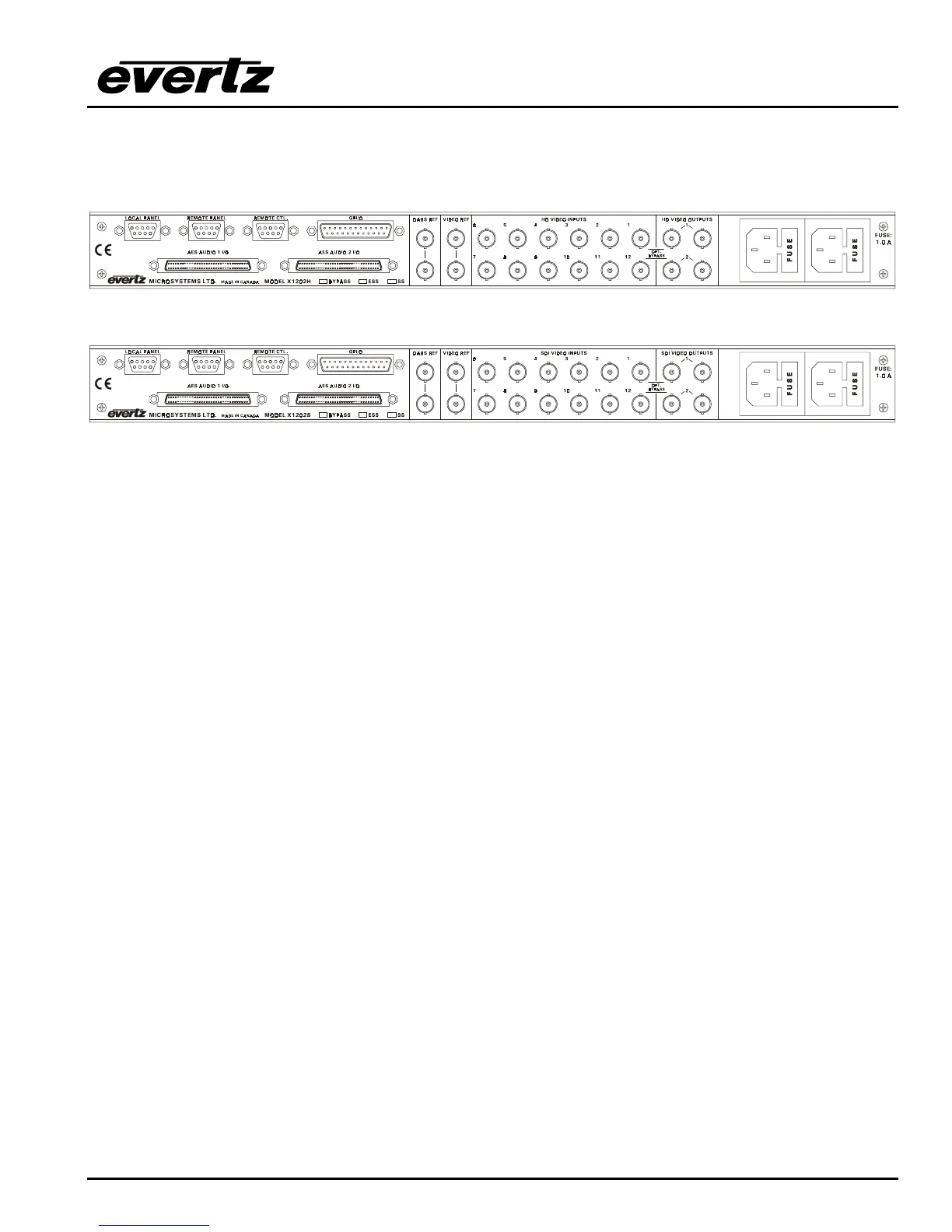
Figure 2-1: X1202H-AES4 Rear Panel Layout
Figure 2-2: X1202S-AES4 Rear Panel Layout
Sections 2.1.1 to 2.1.6 describe the purpose of the rear panel connectors and the specific signals that
should be connected to the routers. Router versions that have SoftSwitch, Embedded SoftSwitch or
Bypass relay options installed will have the option checked (√) on the rear panel. Chapter 6 provides
pictorial representations of the video and audio output configurations for each version of the router.
2.1.1. Standard Definition Digital Video Connections (X1200S)
SDI VIDEO INPUTS 1 to 12 These BNC connectors are for connecting 10-bit serial digital video signals,
compatible with the SMPTE 259M standard to the respective video input buss.
SDI VIDEO OUTPUTS 1 and 2 There are two video output connectors for each of the two video
router busses on X1202S routers. The Video from the selected Video Input buss will be
available on two outputs for each bus. X1201S routers do not have the Second output bus.
When the bypass relay option is fitted, INPUT 1 is protected by a bypass relay to the adjacent
OUTPUT 1 BNC for both X1202S and X1201S routers. INPUT 12 is protected by a bypass
relay to the adjacent OUTPUT 2 BNC on the X1202S routers only. The bypass relays will
activate in the event of power loss to the router and can also be activated from the front panel
menu.
2.1.2. High Definition Digital Video Connections (X1202H)
HD VIDEO INPUTS 1 to 12 These BNC connectors are for connecting 10-bit serial digital video signals,
compatible with the SMPTE 292M standard to the respective video input buss.
HD VIDEO OUTPUTS 1 and 2 There are two video output connectors for each of the two video
router busses. The Video from the selected Video Input buss will be available on two outputs
for each bus.
When the bypass relay option is fitted, INPUT 1 is protected by a bypass relay to the adjacent
OUTPUT 1 BNC and INPUT 12 is protected by a bypass relay to the adjacent OUTPUT 2 BNC.
The bypass relays will activate in the event of power loss to the router and can also be
activated from the front panel menu.
 Loading...