X1200 Series Router Manual
Page 2-8
Revision 1.3.2
INSTALLATION
2.5.1. Connecting the General Purpose Inputs
The GPI’s are used to activate video and audio bus crosspoints and are programmable in a number of
configurations. The GPIs can be configured to operate in one of 3 encoded modes. In these modes,
many of the GPI inputs are pre-assigned to a function. The unused inputs are still available for the user to
assign to a particular function using the Program Gpi’s menu item. When the GPI Encoding is set to none,
all 14 inputs are available for the user to assign to particular functions. Sections 3.12.3.1 to 3.12.3.3
describe how each of the GPI encoding modes works and which inputs are available for user assignment.
When the GPI inputs are independently programmed, they can be set to activate on rising or falling edges,
or high or low levels. The factory default is for low level activation, which means a ground level on the
input will trigger the GPI function when the Opto isolator is normally powered. See Figure 2.2 and 2.3
The high level activation can be used when you need to trigger the GPI function by providing a positive
voltage to a GPI input. This mode is not generally used and should not be considered a first choice.
The falling edge activation is used to trigger a GPI function by removing a provided voltage to a GPI or by
making a closure to ground when the Opto isolator is already powered. The falling edge GPI will respond
the same as a low level activation when the opto isolator is normally powered.
The rising edge activation is used to trigger a GPI function when power is provided to the Opto isolator, or
when the GPI closure to ground is released. This function can be used to trigger a GPI function when a
GPO error tally is released.
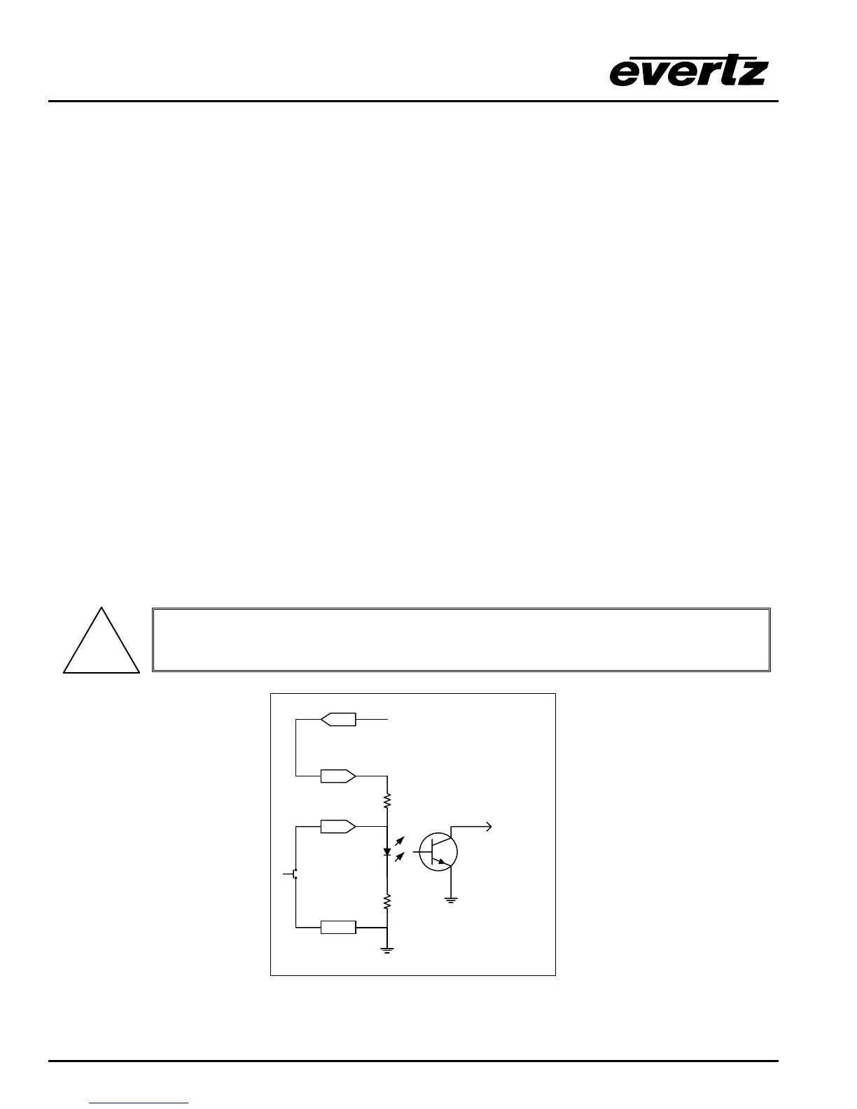
The user can connect GP+5V supplied from the frame (Vint pin) into the Vext pin to provide power to the
GPIO opto-isolator circuitry. In this configuration the user can activate GPIs simply by connecting the GPI
input pins to Ground (see Figure 2-5). This can be done with a button, switch, relay or an open collector
transistor.
!
Warning: Do not connect GP+5V from one frame to another frames GP+5V.
GPI
15
25
GPI
Command
16
+ 5 VDC
to
internal
circuit
4.7 K
220 Ohm
GND
Vext
Figure 2-5: Powering the General Purpose Input Opto-Isolators from the Router