X1200 Series Router Manual
Page 2-10
Revision 1.3.2
INSTALLATION
15
16
Vext
Vint
+5 VDC
11
12
17
18
19
20
21
22
23
24
GND
25
GPI 11
GPI 12
GPO 1
GPO 2
GPO 3
GPO 4
CH 1 Return
Take Input 2 on AFV1 (low level)
Take Input 1 on AFV1 (rising edge)
Input 2 Tally on V1
V1 Output Failure
Input 1 Tally on V1
Input 1 Failure
External Alarm
to indicate
changeover
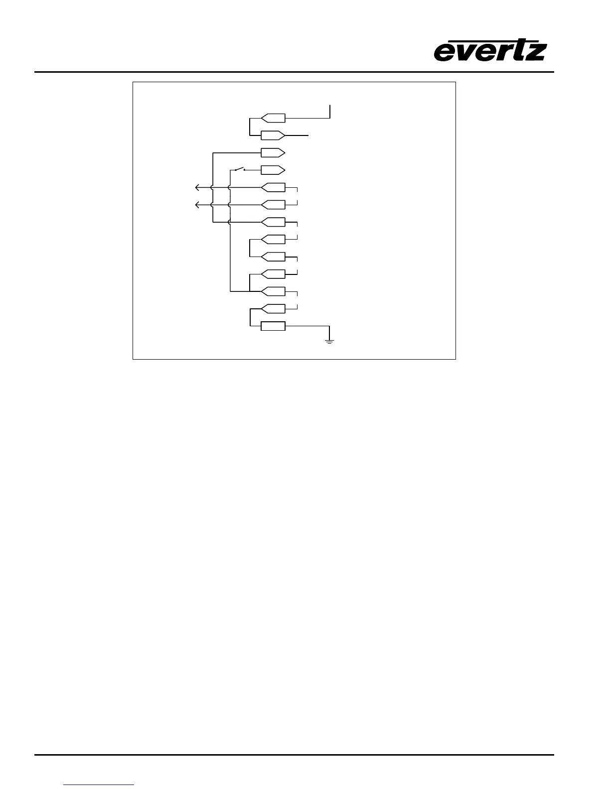
Figure 2-7: GPIO Example – Auto Changeover to Input 2 on Loss of Input 1
If the “CH 1 Return “ switch is closed input 1 will be automatically selected when it is present again. This
has a down side that if the Input 1 signal failure is sporadic the router will chatter between input 1 and 2.
The purpose here is to show the use of a rising edge GPI trigger.
Also interesting to note that this functionality can co-exist with the HEX and AFV HEX GPI encoding as
GPI 11 and 12 are both available for user functions in these encoded GPI modes.
2.6. CONTROLLING THE ROUTER USING THE EXTERNAL SERIAL PROTOCOL
The X1200 series routers can be controlled from router control devices or it can control other devices
employing industry standard router control protocols. Currently the only control protocol supported is the
Grass Valley Ten-XL ASCII protocol. The control device is connected to the router using the
REMOTE CTL connector on the rear panel. The REMOTE CTL menu is used to configure the
REMOTE CTL port for external control using the Baud Rate, Serial Format, Serial Address and Serial
Control menu items. See section 3.14 for information about configuring the REMOTE CTL port
parameters. See chapter 5 for detailed information about controlling the router
2.6.1. Connecting the Router to a Grass Valley Ten XL ASCII Control Device
Use the External control item on the Setup Menu and select Gvg ten xl ASCII protocol. The Baud
Rate, Serial Address, and Serial Format menu settings must be set to match those required by the GVG
control device. If the Router is being controlled by another device set the Serial Control menu setting to
slave. If the router is controlling another device using its remote control port then set the Serial Control
menu setting to master. The REMOTE CTL port is shipped from the factory configured for RS232
operation. If you require RS-422 operation then you will have to change the port wiring as described in
section 2.4.2.