X1200 Series Router Manual
INSTALLATION
Revision 1.3.2
Page 2-5
Pin
#
Name Description
1 GPI 01 General Purpose Input 01
2 GPI 02 General Purpose Input 02
3 GPI 03 General Purpose Input 03
4 GPI 04 General Purpose Input 04
5 GPI 05 General Purpose Input 05
6 GPI 06 General Purpose Input 06
7 GPI 07 General Purpose Input 07
8 GPI 08 General Purpose Input 08
9 GPI 09 General Purpose Input 09
10 GPI 10 General Purpose Input 10
11 GPI 11 General Purpose Input 11
12 GPI 12 General Purpose Input 12
13 GPI 13 General Purpose Input 13
14 GPI 14 General Purpose Input 14
15 Vext External voltage input to power opto isolators
16 Vint Protected +5 volts output from router
17 GPO 01 C General Purpose Output 01 Common contact
18 GPO 01 NC General Purpose Output 01 Normally closed contact
19 GPO 02 C General Purpose Output 02 Common contact
20 GPO 02 NC General Purpose Output 02 Normally closed contact
21 GPO 03 C General Purpose Output 03 Common contact
22 GPO 03 NC General Purpose Output 03 Normally closed contact
23 GPO 04 C General Purpose Output 04 Common contact
24 GPO 04 NC General Purpose Output 04 Normally closed contact
25 GND Router Chassis ground
Table 2-3: GPI/O Pin Definitions
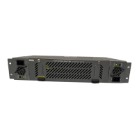
2.1.6. Power Connections
The router has one or two (redundant supply is optional) universal power supplies that operate on either
115 Volt / 60 Hz or 230 Volt / 50 Hz AC.
2.2. MOUNTING
The Router is equipped with rack mounting angles and fits into a standard 19 inch by 1.75 inch by 17.75
inch (483 mm x 45 mm x 451mm) rack space. The mounting angles may be removed if rack mounting is
not desired.
2.3. POWER REQUIREMENTS
2.3.1. Selecting the Correct Mains Voltage
Power requirements are 115 or 230 volts AC at 50 or 60 Hz. The router has a universal power supply that
automatically senses the input voltage. Power should be applied by connecting a 3-wire grounding type
power supply cord to the power entry module on the rear panel. The power cord should be minimum 18
AWG wire size; type SVT marked VW-1, maximum 2.5 m in length. If the router is fitted with the
redundant power supply there will be an additional IEC-320 connector on the rear panel.
 Loading...