X1200 Series Router Manual
Page 2-2
Revision 1.3.2
INSTALLATION
2.1.3. AES Audio Connections
There are two 68 pin connectors used to connect the AES Audio Breakout panels (X1202ABO or
X1201ABO) to the Router. These panels are connected using the cables provided. Each Audio Breakout
Panel has two identical sections consisting of 12 AES inputs and 2 outputs. Earlier versions of the router
may not have either or both audio connectors installed. See sections 2.1.3.1 to 2.1.3.3 for information
about connecting the audio for the version of the router that you have.
!
When connecting the Audio Breakout Panel cables, insert the cable carefully into
the connector on the router and the breakout panel, being careful not to bend the
pins. Press it firmly in place and hand tighten the hold down screws firmly to
provide proper strain relief.
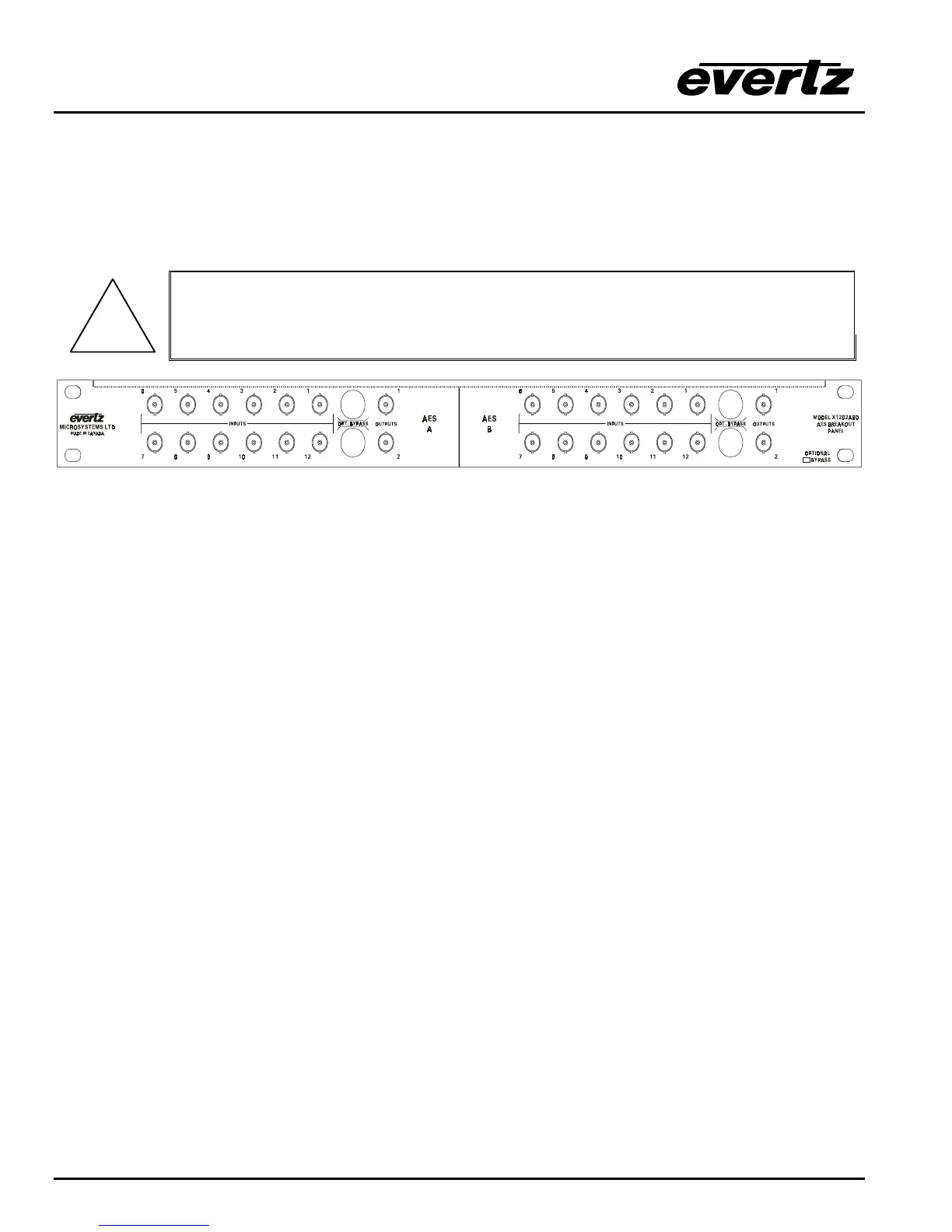
Figure 2-3: X1202ABO Audio Breakout Panel Layout
INPUTS 1 to 12 These BNC connectors are for connecting unbalanced AES audio signals compatible
with the SMPTE 276M standard to the respective audio input buss.
OUTPUTS 1 and 2 These BNC connectors are for connecting unbalanced AES audio signals
compatible with the SMPTE 276M standard from the respective audio input buss.
On the X1202ABO used with the X1202 routers, when the bypass relay option is fitted, INPUT
1 is protected by a bypass relay to the adjacent OUTPUT 1 BNC and INPUT 12 is protected by
a bypass relay to the adjacent OUTPUT 2 BNC. On the X1201ABO used with the X1201
routers, INPUT 1 is protected by a bypass relay to the adjacent OUTPUT 1 BNC. The bypass
relays will activate in the event of power loss to the router and can also be activated from the
front panel menu.
2.1.3.1. Audio Connections on Router Models with the AES Option Fitted.
Routers fitted with the AES option are shipped with one breakout panel. This panel is connected to the
AES AUDIO 1 I/O connector using the cable provided. On the X1202ABO used with the X1202 routers,
inputs for the 1A and 2A busses are on the AES A section of the breakout panel. (See Figure 6-6 and
Figure 6-7) Outputs 1 and 2 of the AES A section are the outputs from the 1A and 2A busses
respectively. Inputs for the 1B and 2B busses are on the AES B section of the breakout panel. Outputs 1
and 2 of the AES B section are the outputs from the 1B and 2B busses respectively. On the X1201ABO
used with the X1201 routers, outputs 1 and 2 are identical. (See Figure 6-2)
2.1.3.2. Audio Connections On Early Router Models With The AES Option Fitted.
(two breakout panels shipped)
Some early versions of the routers with the AES option were shipped with two breakout panels. On these
routers, there are two distinct modes of operation. The AES MODE menu item on the INPUT SETUP
menu is used to select the desired mode.
In the 4(12x1) mode there are four separate 12 x 1-router sections that can be independently assigned to
follow one of the video busses. Routers fitted with the AES option are shipped with one breakout panel.