X1200 Series Router Manual
INSTALLATION
Revision 1.3.2
Page 2-7
2.4.2. Connecting A Second Remote Control Panel
On either the Front Panel Control or Remote Control version of the router a second control panel can be
connected to the REMOTE CONTROL connector using a straight through cable provided. For longer
distances, simply make your own cable of the required length according to the diagram in Table 2-4. The
default configuration of the REMOTE CONTROL port on the router is RS-232. Before connecting the
remote panel the port must be configured as a SMPTE 207M Tributary as shown in Table 2-2. To
reconfigure the port the user must remove the top cover and reposition jumper J26 so that it is on pins 2 &
3 (toward header J23) and move the ribbon. Communications to the remote panel is through a standard
straight through RS-422 connection, so the panel can be located up to 1000 feet from the main electronics
unit. A plug in 12 VDC adapter supplies power for the remote control panel.
2.5. CONNECTING THE GENERAL PURPOSE INPUTS AND OUTPUTS
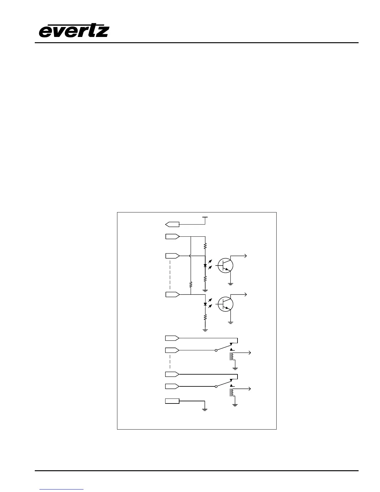
The 25 pin GPI/O connector has 14 programmable general purpose inputs (GPI) and 4 programmable
general purpose outputs (GPO) as shown in Table 2-3. The schematic representation is in Figure 2-4.
The GPIs are opto-isolated inputs that can be powered from an external source or from the frame. The
GPOs are relay contacts that are normally closed when the power to the router is off.
15
16
+ 5 VDC
4.7 K
Vext
GND
1
to
internal
circuit
220 Ohm
14
to
internal
circuit
220 Ohm
4.7 K
GPI 1
GPI 14
Vint
17
18
GPO1 NC*
GPO1 Common
23
24
GPO4 NC*
GPO4 Common
25
from
internal
circuit
from
internal
circuit
*NC Normally Closed with power Off
Figure 2-4: General Purpose I/O Schematic
 Loading...