X1200 Series Router Manual
iv
Revision 1.3.2
CONTENTS
5. SERIAL CONTROL OF THE ROUTERS ......................................................................................... 5-1
5.1. GVG TEN-XL ASCII PROTOCOL ........................................................................................... 5-1
5.1.1. Serial Data Format ....................................................................................................... 5-1
5.1.2. Definitions..................................................................................................................... 5-2
5.1.3. Command Formats....................................................................................................... 5-3
5.1.3.1. Write or Take Command .............................................................................. 5-3
5.1.3.2. Read or Query Command ............................................................................ 5-3
5.1.3.3. Reply Command String ................................................................................ 5-3
5.1.4. Command Examples: ................................................................................................... 5-3
5.1.4.1. Input Selection – Audio Follow Mode........................................................... 5-4
5.1.4.2. Input Selection – Breakaway Mode.............................................................. 5-4
5.1.4.3. Router Status Request................................................................................. 5-4
6. VIDEO AND AUDIO OUTPUT CONFIGURATIONS........................................................................ 6-1
6.1. MODEL X1201 - 12 X 1 OUTPUT CONFIGURATIONS.......................................................... 6-1
6.2. MODEL X1202 - 12 X 2 OUTPUT CONFIGURATIONS.......................................................... 6-3
6.3. MODEL X1202 (EARLY VERSIONS WITH 2 BREAKOUT PANELS)
- 12 X 2 OUTPUT CONFIGURATIONS................................................................................... 6-7
7. VIDEO TIMING CONSIDERATIONS................................................................................................ 7-1
7.1. ALL INPUT SIGNALS ARE TIMED TO REFERENCE. .......................................................... 7-1
7.2. INPUT SIGNALS ARE WITHIN TIMED TO WITHIN +/- 1 LINE OF REFERENCE. ............... 7-2
7.3. ALL INPUT SIGNALS ARE TIMED TOGETHER BUT DELAYED 5 LINES FROM
REFERENCE........................................................................................................................... 7-3
7.4. ALL INPUT SIGNALS ARE TIMED WITHIN A RANGE OF +/- 1 LINE
FROM EACH OTHER BUT DELAYED 5 LINES FROM REFERENCE.................................. 7-4
7.5. ALL INPUT SIGNALS ARE TIMED WITHIN A RANGE OF +/- 1 LINE
FROM EACH OTHER BUT DELAYED 5 LINES FROM REFERENCE.................................. 7-5
Figures
Figure 1-1: X1201 Block Diagram ......................................................................................................... 1-3
Figure 1-2: X1201 SoftSwitch Block Diagram .................................................................................... 1-4
Figure 1-3: X1201 Embedded SoftSwitch Block Diagram.................................................................. 1-4
Figure 1-4: X1202 Block Diagram ......................................................................................................... 1-5
Figure 1-5: X1202 SoftSwitch Block Diagram .................................................................................... 1-5
Figure 1-6: X1202 Embedded SoftSwitch Block Diagram.................................................................. 1-6
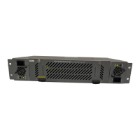
Figure 2-1: X1202H-AES4 Rear Panel Layout...................................................................................... 2-1
Figure 2-2: X1202S-AES4 Rear Panel Layout ...................................................................................... 2-1
Figure 2-3: X1202ABO Audio Breakout Panel Layout .......................................................................... 2-2
Figure 2-4: General Purpose I/O Schematic ......................................................................................... 2-7
Figure 2-5: Powering the General Purpose Input Opto-Isolators from the Router ................................ 2-8
Figure 2-6: Powering the General Purpose Input Opto-Isolators from an External Power Supply........ 2-9
Figure 2-7: GPIO Example – Auto Changeover to Input 2 on Loss of Input 1 .................................... 2-10
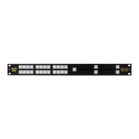
Figure 3-1: Front Panel Layout.............................................................................................................. 3-1
Figure 3-2: Overview of the Setup Menu............................................................................................... 3-4
Figure 3-3: Switch Line Selection in 59.94 Hz Field Rate Systems ...................................................... 3-9
Figure 3-4: Switch Line Selection in 50 Hz Field Rate Systems ......................................................... 3-10