235
POWERHEAD
POWERHEAD ASSEMBLY
11
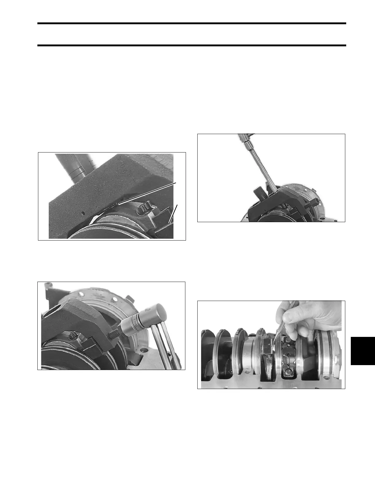
Apply a light coat of outboard lubricant to the cor-
ners of the connecting rod and rod cap. Place
frame on connecting rod using the following pro-
cedure:
• Position frame onto the connecting rod so the
contact area of the jaw is centered on the side
of the rod.
• Tighten forcing screw until jaws contact con-
necting rod.
• Slide frame down until adjustment stop contacts
the rod cap. The groove lines on the jaws must
be centered on the rod/crankpin diameter.
• Tighten the forcing screw to a torque of 23 in.
lbs. (2.5 N·m).
IMPORTANT: Make sure that frame is squarely
in position and that rod and cap are aligned.
Loosen both rod cap screws one-quarter turn.
Use Torquing Socket, P/N 346187, to tighten rod
cap screws in three stages:
• Apply first torque of 40 to 60 in. lbs. (5 to 7 N·m)
to both rod cap screws.
• Tighten screws to a torque of 20 to 22 ft. lbs. (27
to 30 N·m).
• Apply final torque of 60 to 65 ft. lbs. (81 to 88
N·m).
IMPORTANT: If a new screw is used, it must be
installed as above. Then, it must be removed, re-
lubricated, and installed again.
Loosen forcing screw and remove the frame.
Test at least three corners of the rod and cap joint
with a pick. Joint must be smooth with no step.
1. Adjustment stop
2. Groove line
21589
21587
21605
004129