5
Design
EN Rivo™ I Controller
26
W3T597263 Issue 01-0624 | Evoqua Water Technologies GmbH
5DESIGN
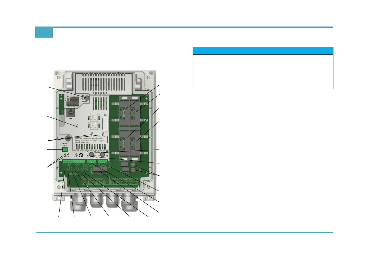
5.1 Rivo™ Backboard 4 (basic housing)
1 Slot for Rivo™ Flex Mod - not used
2 Slot for Rivo™ Flex Mod - not used
3 Slot for Rivo™ Flex Mod - MOD 3 (relay module)
4 Slot for Rivo™ Flex Mod - MOD 4 (mA output module)
5Fuse for relay 2
6Fuse for relay 1
7 Mains fuses
8 Terminals for relay 2
9 Terminals for relay 1
10 PE connection terminals
11 Feedback input for actuator
12 mA input 2
13 mA input 1
14 Temperature input
15 Digital input 2
16 Digital input 1
17 Status LEDs of the digital inputs
18 24V DC connector
19 Status LED of relays K1/K2
20 Status LED
21 24V DC internal fuse
1
3
4
2
5
6
9
8
11
16
15 14 13 12
7
10
17
18
19
20
21
NOTICE
For module configuration, see chapter Installation of
Rivo™ Flex Mod Modules.
Observe assignment of the module slots (sequence).
Status LED states of the Rivo™ Flex Mod Module, see
chapter Description/Function Status LED states.