Description and function
6
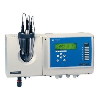
Rivo™ I Controller EN
39
Evoqua Water Technologies GmbH | W3T597263 Issue 01-0624
6.11 Positioner feedback
When a positioner with feedback (positioner with Ym) is
used as dosing output, the actual position of the posi-
tioner/dosing rate is transferred to the control device via
selectable input signals in order to achieve the best pos-
sible control result. Various feedback options are avail-
able:
• Potentiometer 1 kOhm
• Potentiometer 5 kOhm
•0…10V
• 0/4…20mA
The feedback signal used can be set in the menu, see
device. For an optimum control result, the position feed-
back must be aligned (calibrated) with the controller. The
positioner feedback end points 0% and 100% must
always be calibrated. This can be done by running the
automatic positioner calibration function. It can be started
by pressing the “Start” button in the menu, see device.
The controller automatically approaches the 100% and
the 0% position and saves the corresponding values mea-
sured for the feedback signal internally. The positioner
runtime Ty is automatically determined during the calibra-
tion process. During calibration, the positioner must not
be unlocked for manual operation.
If the dosing rates between 0% and 100% are not linear to
the position feedback, these non-linearities can be com-
pensated for or linearized via correction values between 0
and 100%. Up to 11 further positions can be corrected to
compensate for non-linearities in the dosing.
Procedure:
In order to calibrate further data points, select desired cal-
ibration points between 0 and 100% and set the required
dosing output to correct the linearity.
6.12 Digital outputs
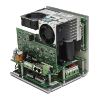
As an option, the electronics module can be equipped with
a Rivo™ Flex Mod 2Rel-2DO. It makes two further relay
outputs and two digital outputs available, which can be
configured as alarm outputs. The digital outputs are opto-
coupler switching outputs for the power-free activation of
dosing devices. The maximum control voltage (external)
of 24 V and a maximum switching current of 20 mA must
be observed here (these digital outputs are not supported
in the Rivo™ I Controller).