7
Installation
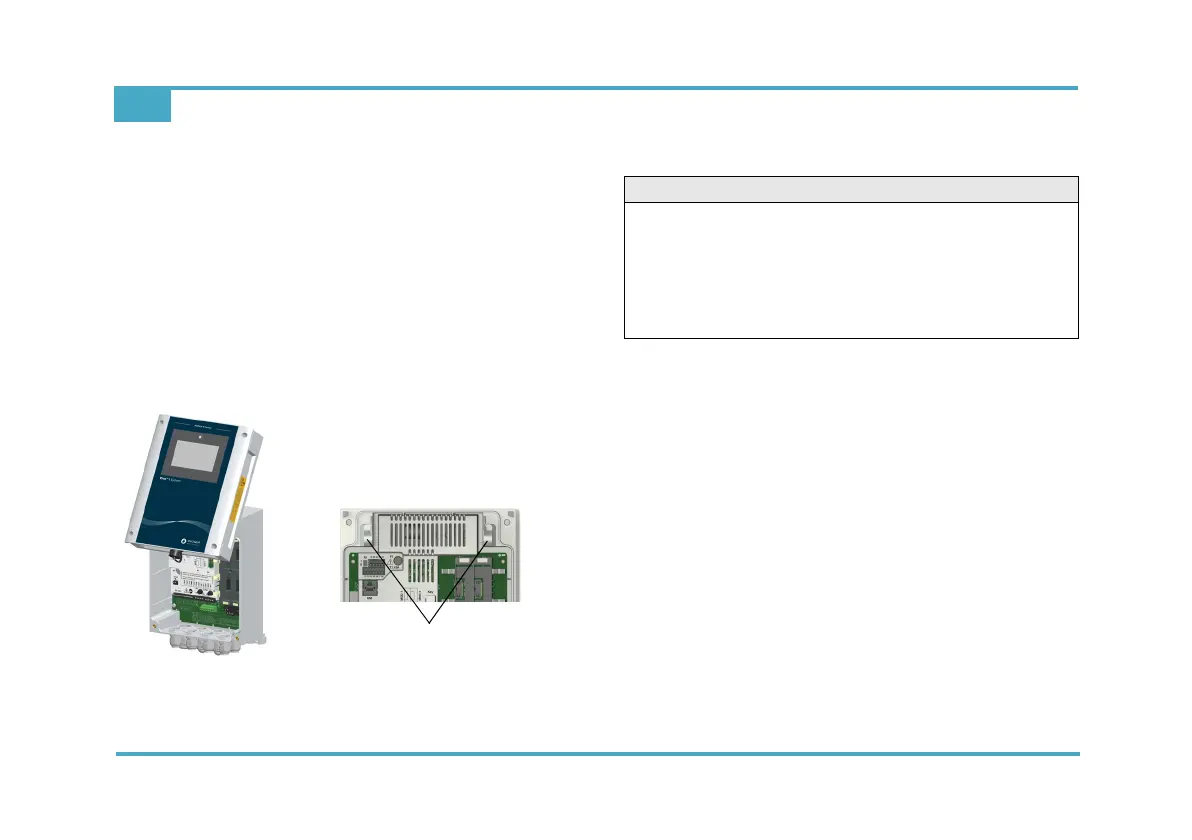
EN Rivo™ I Controller
52
W3T597263 Issue 01-0624 | Evoqua Water Technologies GmbH
7.3 Removing and fitting the housing cover
Removing
1 Release the four screws on the housing cover.
2 Carefully remove the housing cover.
3 Hook the housing cover into the brackets on the basic
housing.
Fitting
1 Carefully unhook the housing cover from the brackets
on the basic housing and fit it onto the basic housing.
2 Tighten the four housing screws by hand (to a maxi-
mum torque of 0.7 Nm ± 0.15 Nm).
Fig. 7 Housing cover hooked on - brackets
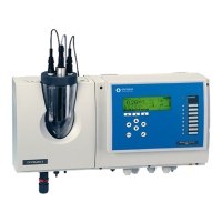
7.4 Installation of Rivo™ Flex Mod Modules
1 Disconnect the Electronics Module from the power
supply and check that it is de-energized.
2 Remove the housing cover of the Electronics module.
3 Insert the Rivo™ Flex Mod Modules into the module
slots provided and ensure that the module locking
mechanism (blue) is engaged and pressed down-
ward.
To dismantle the Rivo™ Flex Mod Module, first pull
the module locking mechanism (blue) upwards and
then remove the module.
Module 1, 2, 3 and 4 allow the installation of the fol-
lowing modules:
Module slot 1: -
Module slot 2: -
Module slot 3: Rivo™ Flex Mod 2Rel 2DO
Module slot 4: Rivo™ Flex Mod 2AO
Brackets on the basic housing
CAUTION
Danger of damage to the Rivo™ Flex Mod Modules
and the HMI
Possible consequence: Significant material damage.
• The Rivo™ Flex Mod Modules and the HMI must not
be plugged in or unplugged with the power supply
switched on.