7
Installation
EN Rivo™ I Controller
54
W3T597263 Issue 01-0624 | Evoqua Water Technologies GmbH
7.5 Remove the battery insulator
Procedure:
1 Fix the battery in the battery holder with a non-con-
ductive pin and pull the battery insulator out to the
left. Ensure that the battery is not pulled out at the
same time.
2 The date and time must be set or checked during
commissioning.
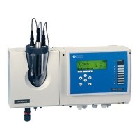
Fig. 10 HMI (housing cover)
1 Battery insulator
7.6 Connecting the Ethernet cable
1 Route the Ethernet cable into the housing through the
M25 cable gland. Only one Ethernet cable can be
connected. Only one cable gland is provided and suit-
able for the insertion of Ethernet connectors (M25 left
side).
2 The other cable glands can be used as required. Mul-
tiple sealing inserts (4x5 mm, 2x6 mm) are included
with the accessories.
3 Plug the Ethernet cable into the HMI as shown in the
wiring diagram.
CAUTION
Danger due to battery insulator
Possible consequence: Material damage
• When commissioning the HMI for the first time, the
battery insulator of the lithium button cell must first
be removed.
NOTICE
• The cable glands on the Electronics Module are
already fitted at the factory.
• Blind plugs are fitted in the cable glands at the fac-
tory. These must be removed during installation in
order to install the corresponding cables.
• For more detailed information, please refer to the
separate installation manual “Rivo™ communica-
tion interfaces”. You can request this installation
manual from us or download it from our homepage.