6
Description and function
EN Rivo™ I Controller
40
W3T597263 Issue 01-0624 | Evoqua Water Technologies GmbH
6.13 Relay outputs
The electronics module has two on-board relays and can
be expanded with relay modules. Further relays can be
added as modules. To do this, the Rivo™ Flex Mod 2Rel-
2DO must be installed. The modules are configured via
the menu setting. These switches are assigned various
switching tasks depending on the respective application.
See the Chapter “Device configuration”.
The connection and switching of non-approved devices/
loads destroys the relay contacts. The device then func-
tions in an uncontrolled manner! In order to switch induc-
tive loads or capacitive loads that exceed the technical
properties of the relay contact, an additional switching ele-
ment such as a contactor or load relay with suitable spec-
ifications must be installed. To suppress radio
interference, the relay contacts are protected internally by
suppressor diodes.
All on-board relays are protected by fuses. They act as
overcurrent limiters protecting the terminal and relay con-
nections. The fuses of the backboard are replaceable
(Type TR5, T3,15A). To fuses of the Rivo™ Flex Mod
2Rel-2DO are not replaceable.
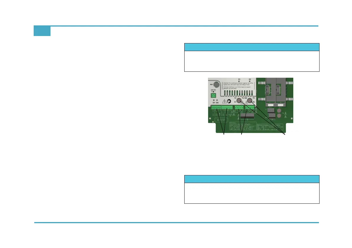
Fig. 5 Detail of PCB - relay outputs
1 Terminal strips for control inputs
2 Terminal strips for relays
3 Fuses of the Rivo™ Backboard 4 relay
NOTICE
If the internal power supply L1 and N/L2 is used for dos-
ing pumps or other devices, the current consumption
must not exceed the value of the selected back-up fuse.
NOTICE
If the internal power supply L1 and N/L2 is used for dos-
ing pumps or other devices, the current consumption
must not exceed the value of the selected back-up fuse.