Contents
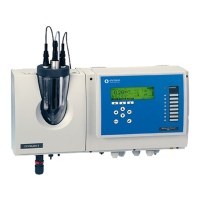
EN Rivo™ I Controller
2
W3T597263 Issue 01-0624 | Evoqua Water Technologies GmbH
6 Description and function .....................28
6.1 General description ........................................28
6.2 Device configuration.......................................29
6.3 Ratio control ...................................................30
6.4 Control parameters ........................................32
6.5 Display of dosing quantity ..............................34
6.6 Digital inputs DI 1 and DI 2 ............................35
6.7 mA inputs, Rivo™ Backboard 4 .....................36
6.8 Connections to visualization systems ............36
6.9 Controller outputs...........................................37
6.9.1 Positioner (with feedback)..............................37
6.9.2 2-point pulse-duration controller for
dosing pumps.................................................37
6.9.3 2-point pulse-frequency controller for
solenoid pumps .............................................38
6.9.4 Analog 2-point output .....................................38
6.10 mA outputs .....................................................38
6.11 Positioner feedback........................................39
6.12 Digital outputs ...............................................39
6.13 Relay outputs .................................................40
6.14 Messages and alarms ....................................41
6.14.1 Configuration..................................................41
6.14.2 Without Acknowledge.....................................42
6.14.3 ACK with reset ...............................................42
6.14.4 Simple ACK....................................................42
6.14.5 Safety functions..............................................43
6.15 Status LED states ..........................................43
6.16 Interfaces .......................................................44
6.16.1 USB interface................................................. 45
6.16.2 Firmware update via USB interface ............... 45
6.16.3 RS485 interface (optional) .............................45
6.16.4 Ethernet interface (HMI)................................. 46
7 Installation ............................................ 48
7.1 Requirements with regard to the
environment and installation location ............. 49
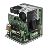
7.2 Installing the electronics module .................... 50
7.2.1 Installation with top-hat rail.............................50
7.2.2 Installation without top-hat rail
(wall installation)............................................. 50
7.2.3 Installation drawing, Electronics Module ........ 51
7.3 Removing and fitting the housing cover ......... 52
7.4 Installation of Rivo™ Flex Mod Modules........52
7.5 Remove the battery insulator ......................... 54
7.6 Connecting the Ethernet cable....................... 54
7.7 Electrical installation....................................... 55
7.8 Firmware update via USB interface ............... 57
7.9 RS485 interface (optional) ............................. 58
8 Start-up ................................................. 60
8.1 Initial commissioning and putting back into
operation ........................................................ 60
9 Shut-down ............................................ 62